Electric Shifter
Special Instructions
None
Special Tools
- Basic hand tools
Component Identification
 |
1. Cap Screw 2. Electric Shifter 3. Gasket |
Procedure - Removal
Remove nylon cable ties from motor wires. Disconnect Transmission Harness from the Rail Select Sensor and the Gear Select Sensor.
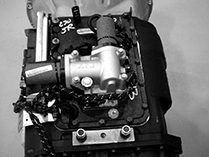
Disconnect the Rail Select and Gear Select Motors from the Transmission ECU (TECU).
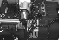
Using a 9/16” socket, remove the 4 mounting cap screws.
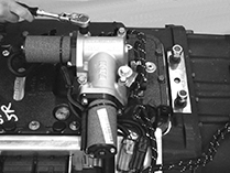
Remove X-Y Shifter and gasket.
Warning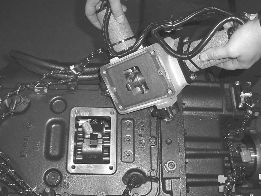
Procedure - Installation
Ensure Shift Blocks are in the neutral position, then move Shift Finger to the center (neutral) location.
Note: If the Shift Finger is not properly aligned, the X-Y Shifter will not fit properly at its mounting location.
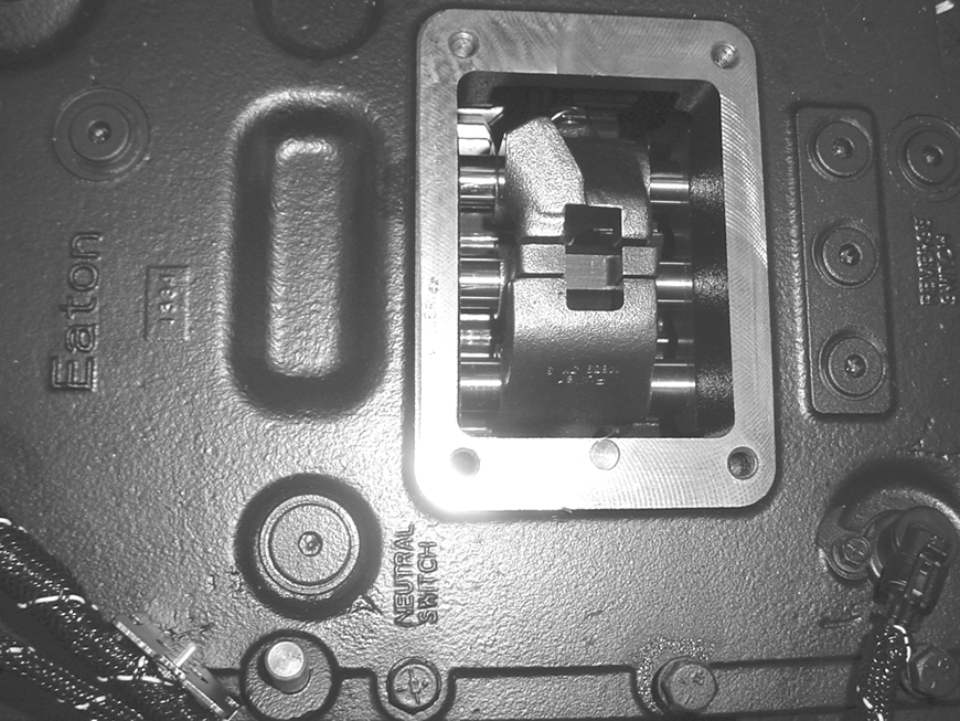
Clean and remove old gasket material from Shift Bar Housing. Then, install new gasket on the Shift Bar Housing.
Note: Apply Eaton sealant part number 71205 or equivalent to the mounting cap screws before installing.
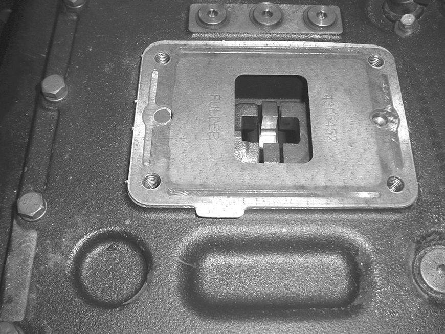
The dowel pin on the X-Y Shifter must be aligned with hole in the Shift Bar Housing (used only on 10-, 13- and 18-Speed models).
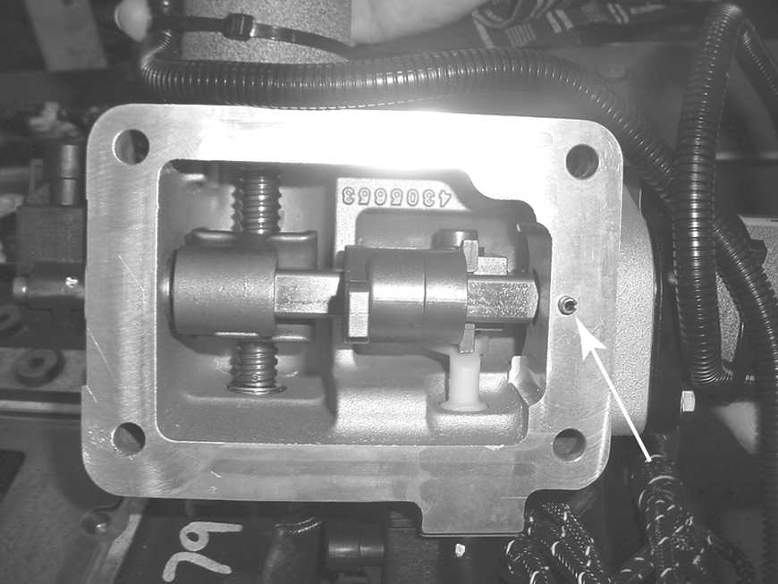
Position X-Y Shifter on the Shift Bar Housing. Using a 9/16” socket, install mounting cap screws and tighten in a cross pattern as follows:
- 5- and 6-Speed (aluminum housing)- Tighten to 20-25 lb-ft. (27-34 Nm).
- 10- 13- and 18-Speed (cast iron housing) - Tighten to 34-45 lb-ft. (45-60 Nm).

Reconnect the Rail Select Sensor and Gear Select Sensor.

Reconnect the Transmission Harness to the Rail Select and Gear Select motors. Using nylon ties, secure motor wires to the transmission in their previous position.

To operate properly, the system must be calibrated as follows:
Notice- Turn ignition switch on. Allow the transmission to power up.
- Turn ignition switch off. Wait 2 minutes.