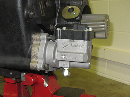
MHP/MXP/VHP/VXP Splitter Cylinder
Special Instructions
During removal on 9-series UltraShift PLUS transmissions the Auxiliary section requires R&R prior to Splitter Cylinder removal. Damage to internal components will result if Auxiliary Section is not properly removed prior to Cylinder removal.
During removal if replacing only the O-Rings in the Splitter Cylinder, Auxiliary Section removal is not necessary
During installation apply Eaton® Lubricant or equivalent to Shift Cylinder Assembly and insert valve O-Rings so a film covers the entire surface of each O-Ring.
During installation apply Eaton® rust preventative #71213 or equivalent to all Shift Cylinder walls and Yoke Bars, cover the entire Yoke Bar surface that comes in contact with the Shift Cylinder O-Ring.
Special Tools
- Typical Service Tools
- Vise with brass jaws or wood blocks
Component Identification
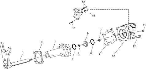 | |
1. Splitter Yoke Assembly 2. Gasket 3. Splitter Cylinder 4. O-Ring 5. Piston 6. O-Ring 7. Nut 8. O-Ring 9. Gasket 10. Splitter Cylinder Cover 11. Pipe Plug | 12. Capscrew 13. O-Ring 14. Hex Flange Head Screw 15. Solenoid Valve |
Splitter Cylinder Removal
Ensure transmission is drained of oil.
Remove retaining cap screws from the Splitter Cylinder Cover
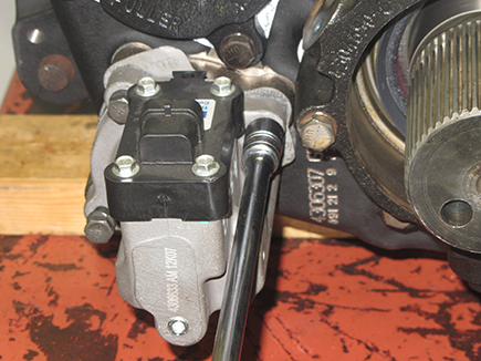
Remove cover and gasket
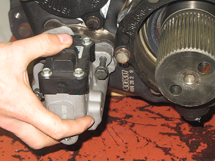
Remove 3/4” nut on the Splitter Yoke Bar.
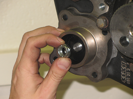
Remove the Splitter Cylinder Housing from the rear of the Auxiliary Case Housing
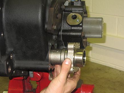
Remove the Piston from the bore of the Splitter Cylinder.
Note: If spool valve needs to be replaced, it must be done as an entire unit which is part of splitter cover
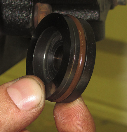
Splitter Cylinder Assembly
Install the Splitter Sliding Clutch on the Splitter Yoke Fork and engage into the Splitter Gear to maintain position.
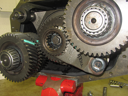
Install small O-ring in the Cylinder Housing Bore if previously removed.
On the Piston O.D., install the Piston O-ring if previously removed.
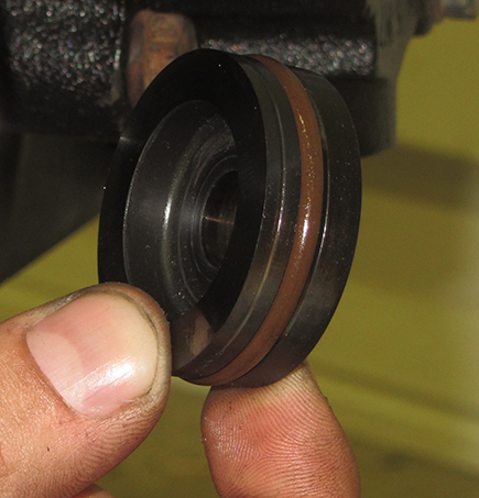
Position new gasket on the Cylinder Housing, and install the Splitter Cylinder
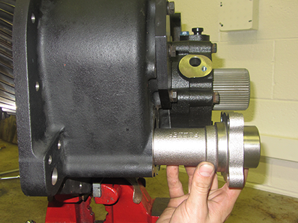
Install O-Ring on the end of the yoke bar inside of the Cylinder Housing
Install new O-rings on the ID and OD of the piston, then lubricate with silicone.
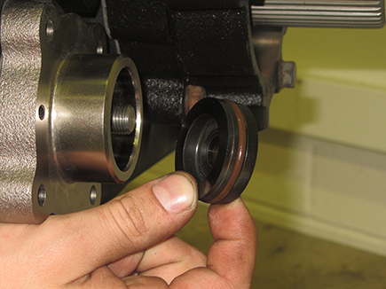
Install the piston into the Splitter Cylinder with the recessed side facing the rear of the transmission.
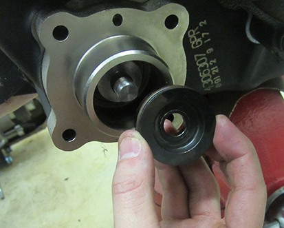
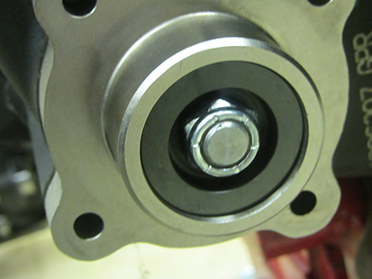
Secure piston with the 3/4 lock nut. Torque to 30-36 lb-ft (41-49N•m).
Position new gasket on the Cylinder Housing Cover mounting surface and install the Splitter Cylinder Cover
Note: Ensure that the gasket air passage aligns with the housing air passage
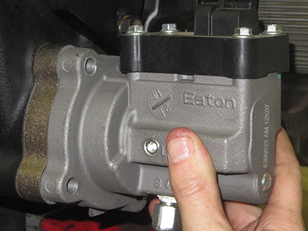
Apply Eaton Sealant #71205 or equivalent to the retaining cap screws, and install on the cover. Torque to 20-25 lb-ft.
