UltraShift PLUS
TRSM0940 EN-US
|
March 2024 - A
Input Shaft Speed Sensor
Special Instructions
None
Special Tools
- Basic hand tools
Component Identification
 |
1. 2-Way Input Shaft Speed Sensor |
Input Shaft Speed Sensor Removal
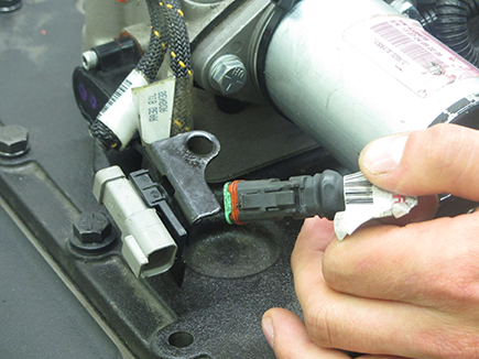
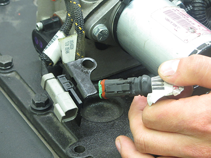
Disconnect the Transmission Harness from the Input Shaft Speed Sensor or pigtail connector, if equipped.
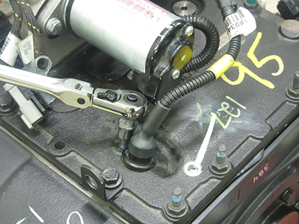
Using a 3/8” socket, remove the sensor retaining bolt.
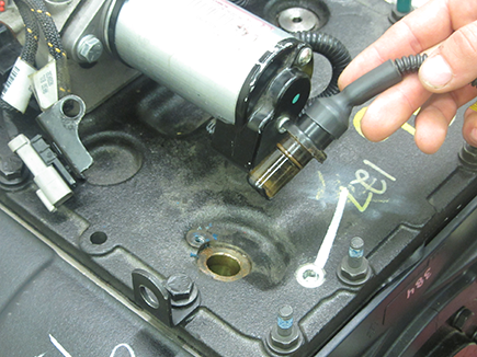
Remove the Input Shaft Speed Sensor, with O-ring, from the Transmission Shift Bar Housing.
Input Shaft Speed Sensor Installation
Notice
Notice
Using a smooth, twisting motion, fully insert the Input Shaft Speed Sensor in the Transmission Shift Bar Housing opening.
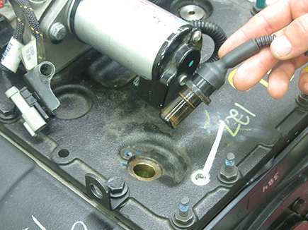
Using a 3/8” socket, install the retaining bolt and tighten to 8–10 lb-ft (11–13 N•m).
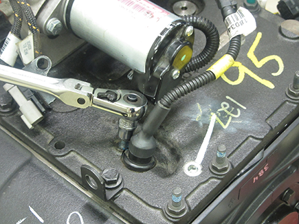
Reconnect the Transmission Harness to the Input Shaft Speed Sensor or pigtail connector, if equipped.
