Clutch
Special Instructions
Install Clutch Alignment Shaft (RR1087TR) onto a clutch jack. Refer to clutch jack manufacturer guidelines for proper installation instructions.
- Fault Code 250 to set Active
- "CC" in display and may not complete a Clutch Calibration
Special Tools
- Clutch Installation Tool Kit (RR2000CL)
- 6 ounce (170 gram) hammer
- 3/8 inch (9.525 mm) brass pin punch (Starrett® B248E Pin Punch, Brass Drive 3/8" or equivalent)
- Input Shaft Pilot Bearing Wear Sleeve Puller (RR1062TR)
- Wear Sleeve Installer (RR1061TR)
- Snap Ring Installer (RR1061TR-1)
- Wear Sleeve Driver (RR1061TR-2)
- Vernier Caliper
- Steel straight edge 300mm (12 inch) long with a minimum thickness of 6.35mm (1/4 inch) - (12” Veritas Steel Straightedge or equivalent)
Component Identification
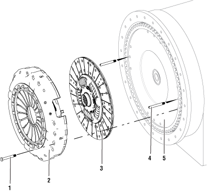 | |
1. Clutch Cover Cap Screws (x12) M10 x 1.5 x 80mm, minimum class 10.9, flange type fasteners 2. Clutch Cover | 3. Driven Disc Assembly 4. Alignment Pins (x2) 5. Engine Flywheel |
Create a Service Activity Report
Note: If not already created and sent.
Key on with engine off.
Connect ServiceRanger and create a Service Activity Report.
Select “Send to Eaton” (internet connection required)
Disconnect ServiceRanger.
Key off.
Manually Vent Linear Clutch Actuator (LCA)
Key off.
Set vehicle parking brake and chock wheels.
WarningLoosen the 4 Linear Clutch Actuator (LCA) cap screws 1-2 turns each with a T45 Torx.
Note: Residual air pressure in the LCA cylinder exhausts between the LCA and Mechatronic Transmission Module (MTM) housing when the cap screws are loosened.
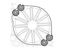
Tighten the 4 LCA to MTM T45 cap screws and torque to 23-27 Nm (17-21 lb-ft).
Remove the Transmission
Disconnect negative battery cable.
Refer to OEM guidelines for transmission removal.
Remove the Clutch
Remove the 4 center 15 mm Clutch Cover cap screws from each of the 3-bolt groups.
Warning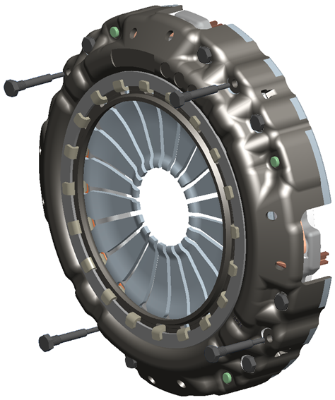
Install and hand tighten the 4 stand-off bolts (RR1063TR-4) in place of the removed Clutch Cover cap screws.
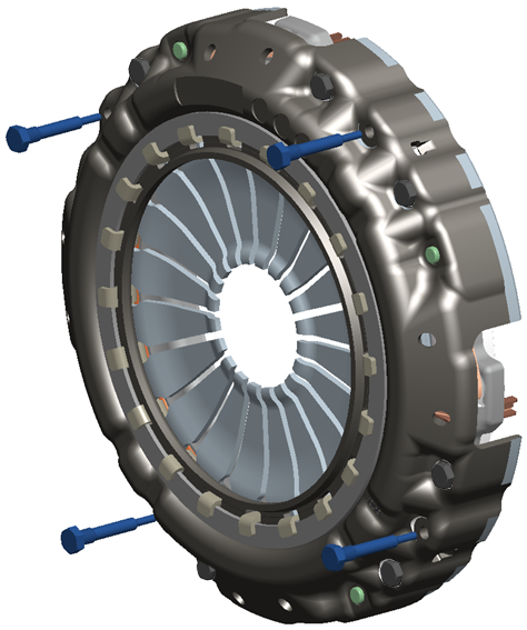
Insert the clutch jack-mounted Clutch Alignment Shaft (RR1087TR) into the clutch diaphragm spring and pilot bearing.
Warning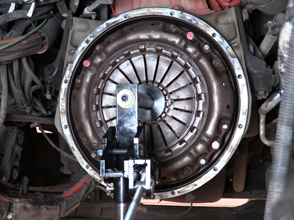
Remove the 8 remaining 15 mm Clutch Cover cap screws.
NoticeRemove the Clutch Cover and Driven Disc from the flywheel.
Engine Flywheel and Housing Inspection
- Fault Code 250 to set Active
- "CC" in display and may not complete a Clutch Calibration
Remove the pilot bearing.
Verify flywheel face runout.
Secure the dial indicator base to the flywheel housing face with the dial indicator finger in contact with the flywheel face near the outer diameter.
Note: Clean all dial indicator contact surfaces.
Rotate flywheel one revolution and record flywheel face runout: maximum runout is 0.008" (0.20 mm).
Notice
Verify pilot bearing bore runout.
Secure the dial indicator base to the flywheel housing face with the dial indicator finger in contact with the pilot bearing bore.
Note: Clean all dial indicator contact surfaces.
Rotate flywheel one revolution and record pilot bearing bore runout: maximum runout is 0.005" (0.13 mm).
Notice
Verify flywheel housing inner diameter (ID) runout.
Secure the dial indicator base to the crankshaft with the dial indicator finger in contact with the flywheel housing ID.
Note: Clean all dial indicator contact surfaces.
Rotate crankshaft one revolution and record flywheel housing (ID) runout: maximum runout is 0.008" (0.20 mm).
Notice
Verify flywheel housing face runout.
Secure the dial indicator base to the flywheel face near the outer diameter with the dial indicator finger in contact with the face of the flywheel housing.
Note: Clean all dial indicator contact surfaces.
Rotate flywheel one revolution and record flywheel housing face runout: maximum runout is 0.008" (0.20 mm).
Notice
Install the Clutch
Install a new pilot bearing. Refer to OEM and/or engine manufacturer installation guidelines.
Install 2 Alignment Pins (RR1063TR-3) into the flywheel directly across from each other, at approximately 3 and 9 o’clock.
Note: Do not install the Alignment Pins into the center threaded hole of the 3-threaded hole groups.
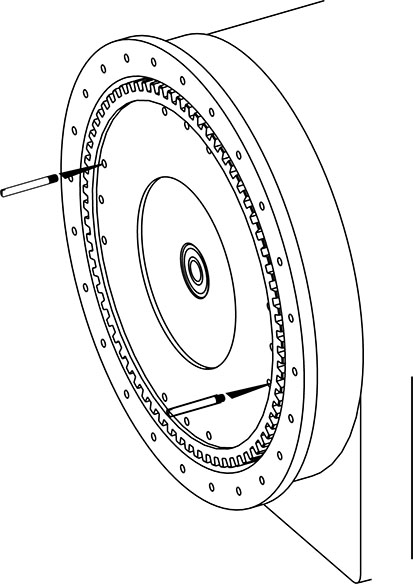
Install the Clutch Cover and Driven Disc onto the clutch jack-mounted Clutch Alignment Shaft (RR1087TR).
Warning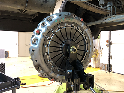
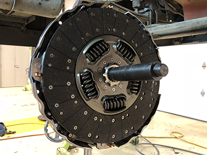
Align the Clutch Cover to the flywheel Alignment Pins and insert the Clutch Alignment Shaft (RR1087TR) into the Pilot Bearing.
Slide Clutch Cover and Driven Disc on to the flywheel and install 6 Clutch Cover cap screws at the 5, 6, 7, 10, 11 and 12 positions (refer to cap screw callout image below). Torque finger tight plus 1/2 rotation clockwise.
NoticeCaution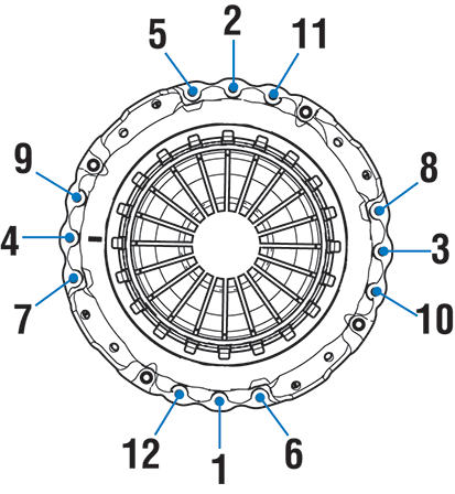
Remove the Clutch Alignment Shaft (RR1087TR).
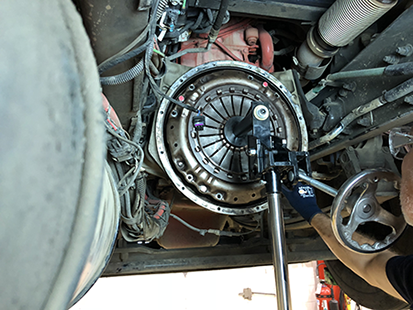
Remove the 2 Alignment Pins (RR1063TR-3), 4 stand-off bolts (RR1063TR-4) and straps (if equipped) from the Clutch Cover.
Install 6 remaining Clutch Cover cap screws finger tight.
Torque Clutch Cover cap screws 1 through 4 to 30 Nm (23 lb-ft) as shown in the torque sequence below.
Caution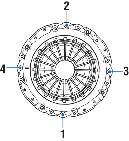
Torque Clutch Cover cap screws 5 through 12 to 30 Nm (23 lb-ft) as shown in the torque sequence below.
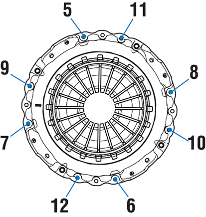
Torque Clutch Cover cap screws 1 through 12 to 57-67 Nm (42-50 lb-ft) as shown in the torque sequence below.

Re-torque Clutch Cover cap screws 1 through 12 to 57-67 Nm (42-50 lb-ft) as shown in the torque sequence below to verify clutch is fully seated to the flywheel.

Locate the 4 Control Fingers in the Clutch Cover.
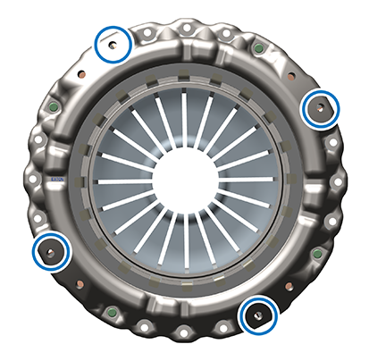
Use a 6 ounce (170 gram) hammer and a 3/8 inch (9.525 mm) brass pin punch and lightly tap the 4 control fingers until they contact the flywheel.
CautionNotice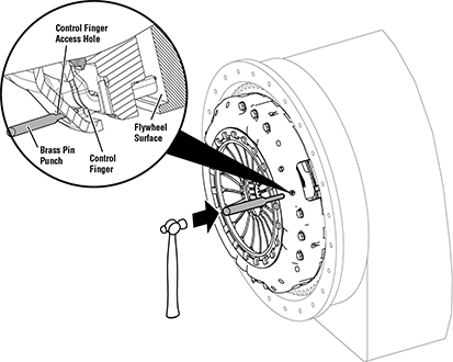
Measure Diaphragm Spring Finger Height
Special Tools
- Vernier Caliper
- Steel straight edge 300mm (12 inch) long with a minimum thickness of 6.35mm (1/4 inch)
Zero caliper to straight edge thickness.
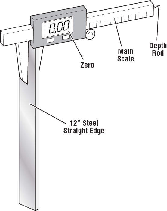
Place straight edge across clutch cover inner-ring.
Note: Ensure straight-edge is seated flat on inner-ring and not contacting other parts of the clutch cover.
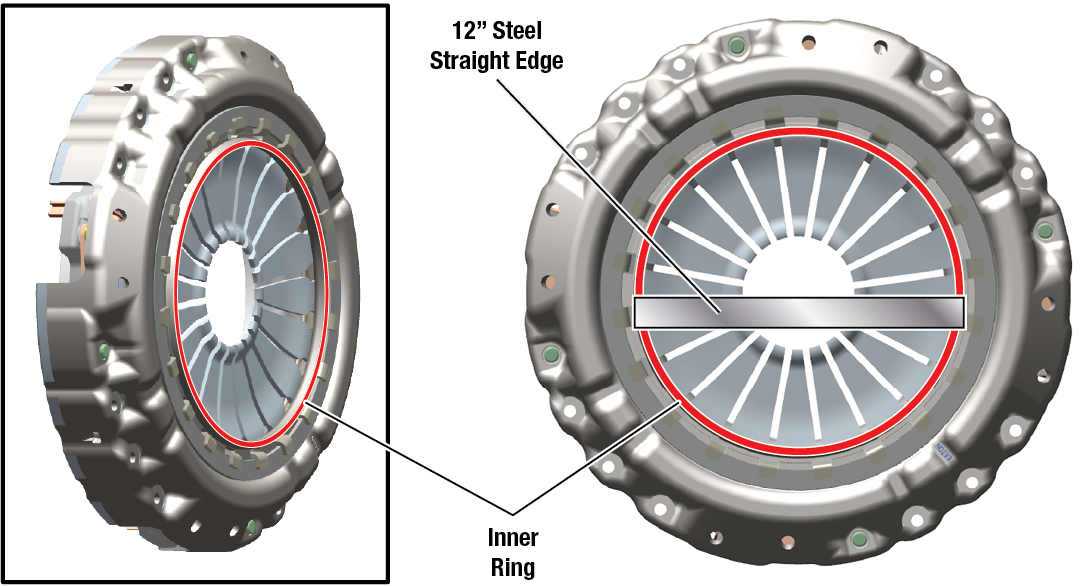
Place caliper "main scale" on straight edge and extend caliper "depth rod" toward one diaphragm spring tip.
Note: Ensure straight-edge is seated flat on inner-ring and not contacting other parts of the clutch cover. Ensure caliper is perpendicular to straight edge. Finger height must be measured at 4 locations.
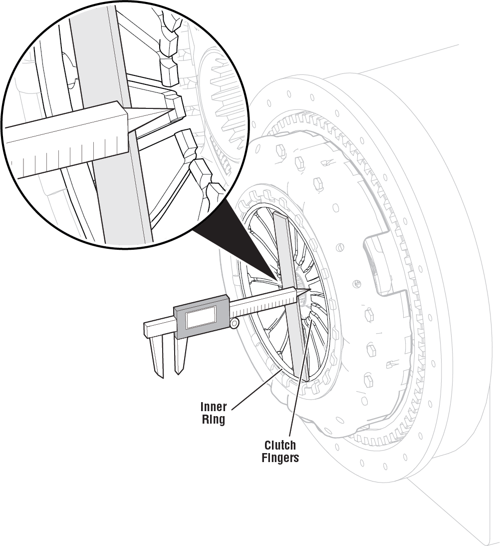
Record finger height measurements at 4 locations.
- Record reading in table - Measurement 1.
- For Measurement 2, place caliper "main scale" on straight edge 180 degrees from Measurement 1. Record reading in table - Measurement 2.
- Repeat this process with the straight edge perpendicular and record reading in table - Measurement 3.
- For Measurement 4, place caliper "main scale" on straight edge 180 degrees from Measurement 3. Record reading in table - Measurement 4.
Note: Ensure straight-edge is seated flat on inner-ring and not contacting other parts of the clutch cover. Ensure caliper is perpendicular to straight edge. Finger height must be measured in all 4 locations as illustrated.
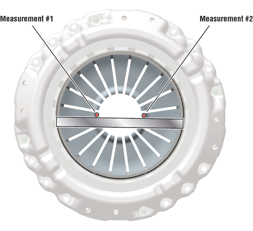
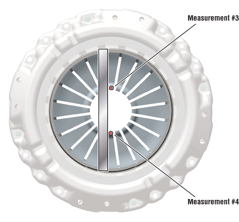
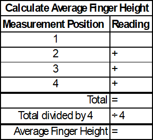
Record engine manufacturer.
- For all Cummins engines, go to Step 6.
- For all other engines (not Cummins), go to Step 7.
Record Average Finger Height calculated in Step 4 and compare reading(s) in table based on clutch condition.
- If readings are in range, process complete.
- If readings are out of range, contact Eaton Cummins Automated Transmission Technologies at +1-800-826-4357 for further diagnostic instructions.
CautionNoticeCummins Engines
Clutch Condition
Finger Height
New Install
17mm - 21mm (0.669 - 0.827 inch)
Less than 160,934 km (100,000 miles)
17mm - 22mm (0.669 - 0.866 inch)
Greater than 160,934 km (100,000 miles)
17mm - 24mm (0.669 - 0.944 inch)
Record Average Finger Height calculated in Step 4 and compare reading(s) in table based on clutch condition.
- If readings are in range, process complete.
- If readings are out of range, contact Eaton Cummins Automated Transmission Technologies at +1-800-826-4357 for further diagnostic instructions.
NoticeAll other engines (not Cummins)
Clutch Condition
Finger Height
New Install
15mm - 21mm (0.591 - 0.827 inch)
Less than 160,934 km (100,000 miles)
15mm - 22mm (0.591 - 0.866 inch)
Greater than 160,934 km (100,000 miles)
15mm - 24mm (0.591 - 0.944 inch)
Disassemble the Input Shaft Pilot Bearing Wear Sleeve
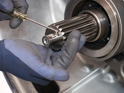
Remove the Spiral Snap Ring from the input shaft with a pick.
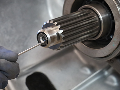
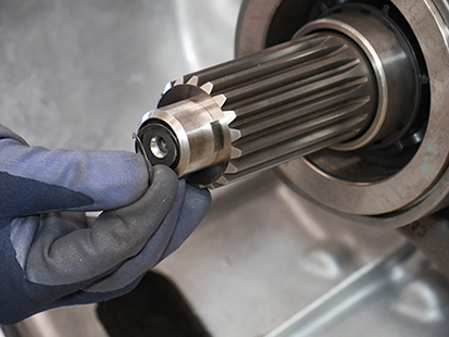
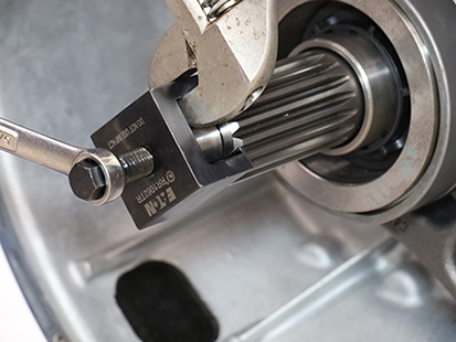
Install the Input Shaft Pilot Bearing Wear Sleeve Puller (RR1062TR) over the flats on the Pilot Bearing Wear Sleeve.
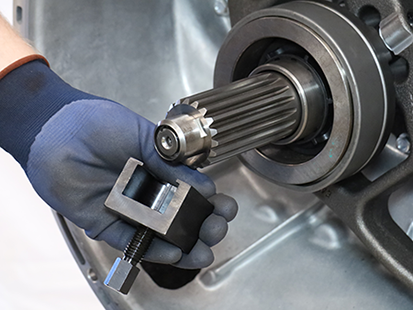
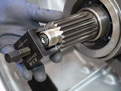
Tighten the 13 mm jackscrew on the Input Shaft Pilot Bearing Wear Sleeve Puller (RR1062TR) to remove Wear Sleeve.
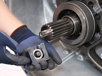
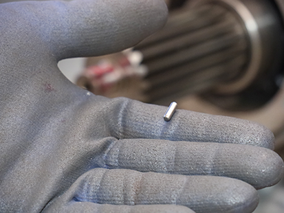
Remove the Wear Sleeve Alignment Pin.
Assemble the Input Shaft Pilot Bearing Wear Sleeve
Clean the Pilot Bearing Wear Sleeve surfaces on the input shaft.
Apply grease to alignment pin groove on the input shaft to hold the Wear Sleeve Alignment Pin in place.
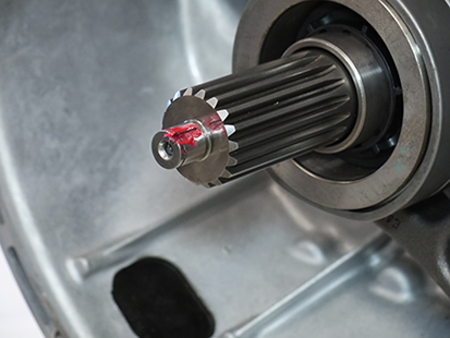
Slide the Wear Sleeve Alignment Pin into the groove on the input shaft.
Notice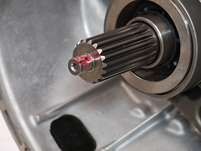
Align the groove in the Pilot Bearing Wear Sleeve with the Wear Sleeve Alignment Pin.
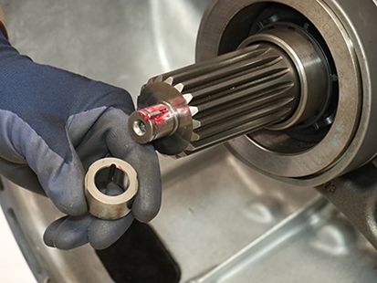
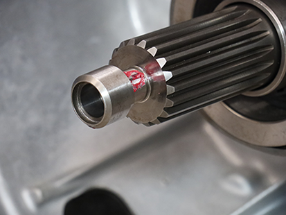
Hold the Pilot Bearing Wear Sleeve against the input shaft and lightly tap with a soft-faced hammer to start installation.
Caution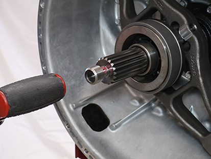
Use the Wear Sleeve Driver (RR1061TR-2) to fully seat the Pilot Bearing Wear Sleeve onto the input shaft.
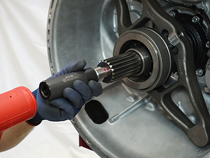
Inspect the Pilot Bearing Wear Sleeve to ensure it is fully seated on the input shaft.
Notice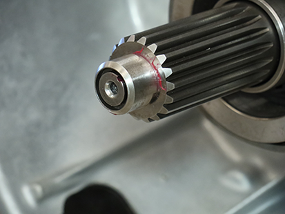
Install a new Spiral Snap Ring onto the Snap Ring Installer (RR1061TR-1).
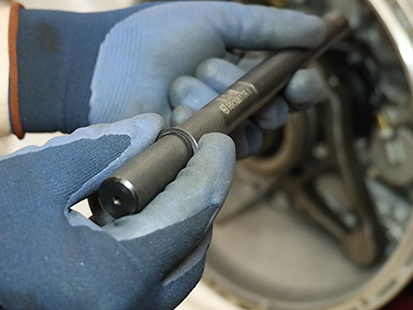
Slide the Wear Sleeve Driver (RR1061TR-2) over the Snap Ring Installer (RR1061TR-1).
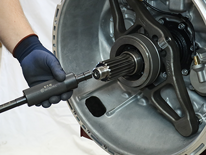
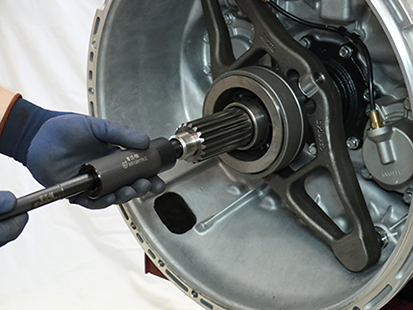
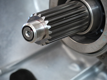
While holding the Snap Ring Installer (RR1061TR-1) against the input shaft, slide the Wear Sleeve Driver (RR1061TR-2) forward and fully seat the Spiral Snap Ring into the snap ring groove.
Remove the Linear Clutch Actuator (LCA)
Loosen the 4 LCA cap screws 1-2 turns each with a T45 Torx.
NoticeNote: Residual air pressure in the LCA cylinder exhausts between the LCA and MTM housing when the cap screws are loosened.
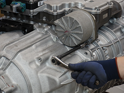
Remove the 4 LCA cap screws
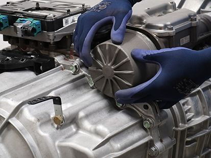
Remove the LCA from the MTM.
Note: LCA piston rod end is seated in the release yoke socket; pull to release rod end from socket.
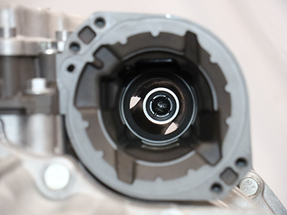
Inspect the plastic socket insert in the release yoke through the LCA opening using a flashlight to verify none of the fingers are missing or damaged.
Note: If the plastic insert is damaged, replace the release yoke assembly.
Reset and Install Linear Clutch Actuator (LCA)
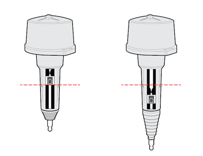
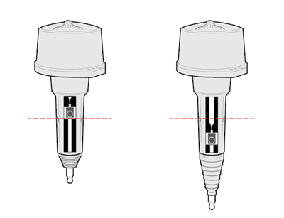
Inspect LCA to determine next steps, reference images below:
- If LCA is locked in the reset position, go to Install Linear Clutch Actuator (LCA).
- If LCA is not locked in the reset position, go to Step 2.
Locked in Reset Position
Not Locked in Reset Position
Place LCA push rod on a clean, flat surface. Tightly grasp LCA housing with both hands and push down on push rod to lock LCA into the reset position.
Caution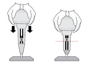
Inspect LCA to determine next steps, reference images below:
- If LCA remains locked in the reset position, go to Step 4.
- If LCA does not remain locked in the reset position, go to Step 2, repeat reset procedure.
Note: If LCA cannot be locked into the reset position, replace LCA.
CautionLocked in Reset Position
Not Locked in Reset Position
Clean all sealing surfaces on the MTM and LCA with a lint free cloth.
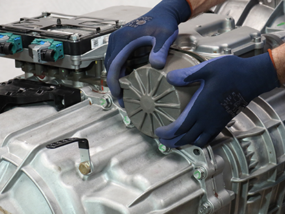
NoticeInsert the LCA into the MTM.
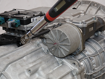
Install 4 LCA T45 cap screws and torque to 23-28 Nm (17-21 lb-ft) in a criss-cross pattern.
Install the Release Bearing and Clutch Release Yoke
Install the upper Release Yoke socket over the rod end of the Linear Clutch Actuator (LCA) and press until attached.
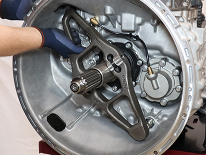
Install the lower Release Yoke socket over the lower pivot on the clutch housing and press until attached.
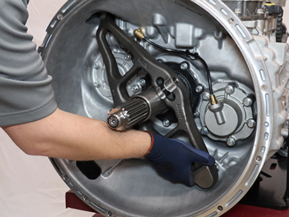
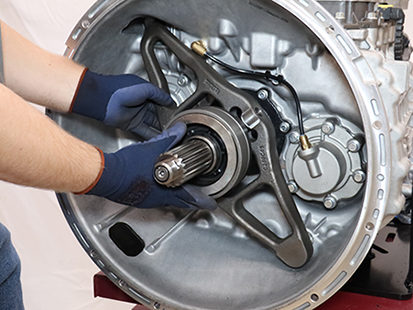
Slide the Release Bearing over the input shaft and into the Release Yoke.
Install the Transmission
Refer to OEM guidelines for transmission installation.
Connect negative battery cable.
Determine next step.
- If transmission oil was not drained, go to Clutch and Rail Calibration.
- If transmission oil was drained, go to Fill Oil.
Fill Oil
Note: Perform the transmission fill procedure with transmission installed in vehicle to ensure proper transmission angle.
Remove the Oil Fill Plug with a 6 mm hex key.
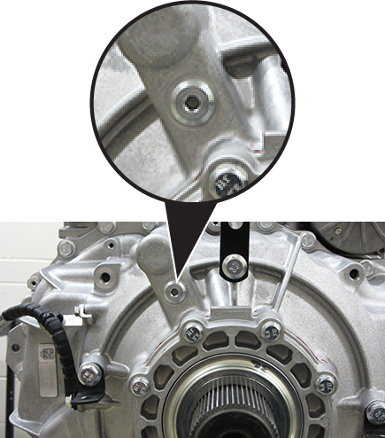
Place a suitable container under the Oil Check Plug and remove the Oil Check Plug with a 6 mm hex key.
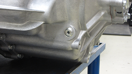
Fill the transmission with PS-386 lube until a small amount of oil runs out of the Oil Check Plug hole.
Note: Fill capacity is approximately 7.5-8.5 liters (16-18 pints) depending on the transmission angle.
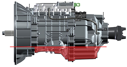
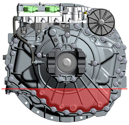
Inspect Oil Check Plug and O-ring for damage. If damaged, replace the Oil Check Plug; O-ring is serviced with plug.
Install the Oil Check Plug (6 mm) and torque to 24.5-29.5 Nm (18-22 lb-ft).
Notice
Inspect Oil Fill Plug and O-ring for damage. If damaged, replace the Oil Fill Plug; O-ring is serviced with plug.
Install the Oil Fill Plug (6 mm) and torque to 24.5-29.5 Nm (18-22 lb-ft).
Notice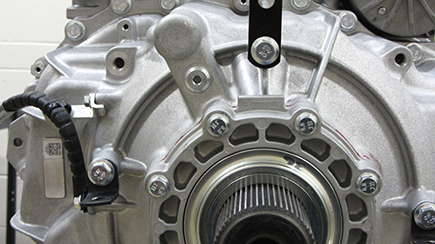
Clutch and Rail Calibration
To ensure proper operation, the TCM, clutch, MTM and transmission require a Clutch and Rail Calibration. Calibrations are automatically initiated when:
- LCA is in the reset position
- Transmission in “N” (Neutral)
- Key on engine running
- Vehicle air system pressure at operating range
Note: Vehicle display may indicate a flashing “CC” and “F” in gear display.
Set vehicle parking brake and chock wheels.
Ensure the driveline is connected between the transmission and axle.
Note: Clutch and Rail Calibrations cannot complete if the transmission output shaft is allowed to rotate.
Key on with engine running.
Allow vehicle air pressure to build to governor cut-off.
Note: Clutch and Rail Calibrations automatically initiate when vehicle air pressure reaches approximately 100 psi.
Ensure “N” (Neutral) is selected and engine is running. Wait approximately 2 minutes for calibrations to complete.
Notice- If vehicle display indicates a solid “N: (Neutral) in gear display, calibrations are complete. Key off, go to Step 6.
- If vehicle display continues to indicate a flashing “CC” and/or “F” in gear display or service transmission message, go to Step 5.
Key off and wait 1 minute.
Key on with engine off.
Connect ServiceRanger.
Go to “Fault Codes”.
- If an Active transmission fault code is set, go to Endurant HD Troubleshooting Guide TRTS0950 Diagnostic Procedure.
- If no Active transmission fault codes are set, select “Clear Eaton Faults” and follow on-screen prompts. Go to Step 9.
Disconnect ServiceRanger.
Key off.
Determine next step.
- If transmission oil was not drained, process complete.
- If transmission oil was drained, go to Step 12.
Inspect transmission for a PTO.
- If not PTO-equipped, process complete.
- If PTO-equipped, start the engine and run for 1 to 2 minutes to fill the PTO with oil, key off and repeat the Fill Oil Procedure.
Caution