Input Shaft
Special Instructions
- Input Shaft replacement requires transmission to be disassembled. Perform Main Shaft and Countershaft Service Procedure to access Input Shaft.
- Clutch Housing is approximately 558 mm (22 inches) wide. Only perform steps to Disassemble/Assemble the Input Shaft when using a press. If the Clutch Housing is too large for the available press, perform steps to Manually Disassemble/Assemble Input Shaft with Input Shaft Press (RR1085TR).
Special Tools
- Input Shaft Cup (RR1085TR-6)
- Input Shaft Stand (RR1073TR)
- Input Shaft Bearing Removal and Installation Tool (RR1075TR)
- Universal Driver Handle (OE8044-T0)
Note: If manually pressing the Input Shaft, additional tools are needed.
- Input Shaft Press (RR1085TR)
- Front Bearing Capture Plate (RR1085TR-7)
- Input Bearing Driver (RR1049TR)
- 4 (2 inch 7/16 inch Grade 8 or 50.8 mm M12 Grade 10.9) cap screws, washers and nuts
Component Identification
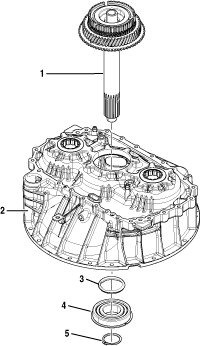 |
1. Input Shaft Assembly 2. Clutch Housing 3. Input Shaft Bearing O-ring 4. Input Shaft Bearing 5. Input Shaft Snap Ring |
Disassemble the Input Shaft
Ensure Input Shaft Snap Ring is removed.
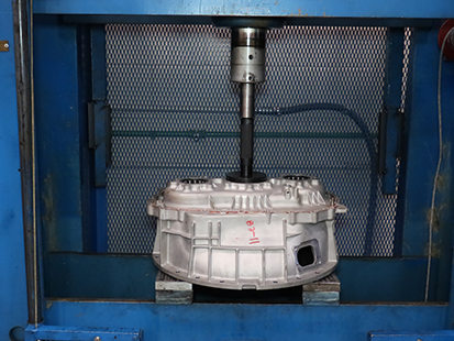
Place Clutch Housing in press with Input Shaft up.
CautionNoticeNoticeNote: Clutch Housing is approximately 558 mm (22 inches) wide. If the Clutch Housing is too large for the available press, perform steps to Manually Disassemble Input Shaft with Input Shaft Press (RR1085TR).
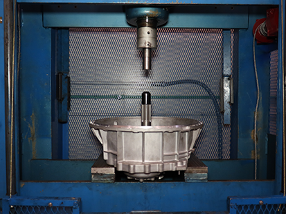
Place Input Shaft Cup (RR1085TR-6 on the end of the Input Shaft.
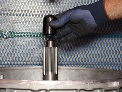
Press Input Shaft from Clutch Housing.
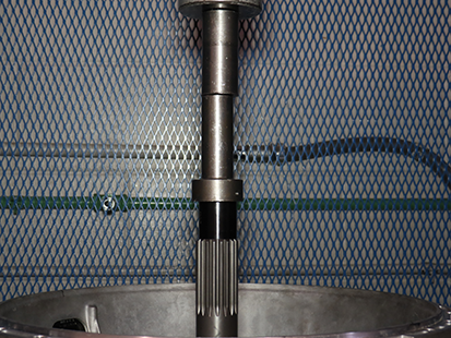
Place Clutch Housing in press with flywheel housing side of the Clutch Housing down.
NoticePlace Input Shaft Bearing Removal and Installation Tool (RR1075TR) and Universal Driver Handle (OE8044-T0) onto Input Shaft Bearing.
Press Input Shaft Bearing from Clutch Housing.
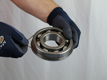
If present, remove Input Shaft Bearing O-ring and discard.
Note: Install a new Input Shaft Bearing O-ring when assembling Clutch Housing with chamfered bearing bores.
Assemble the Input Shaft
Place Clutch Housing in press with flywheel housing side up.
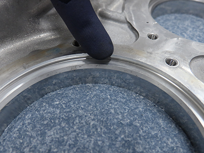
NoticeInspect Input Shaft bearing bore for chamfered edge.
- If chamfer is present, go to Step 3.
- If chamfer is NOT present, go to Step 4.
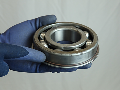
Slide Input Shaft Bearing O-ring on Input Shaft Bearing until fully seated against snap ring.
Note: Install a new Input Shaft Bearing O-ring when assembling Clutch Housing with chamfered bearing bores.

Place Input Shaft Bearing Removal and Installation Tool (RR1075TR) and Universal Driver Handle (OE8044-T0) onto Input Shaft Bearing.
Press Input Shaft Bearing into Clutch Housing.
Notice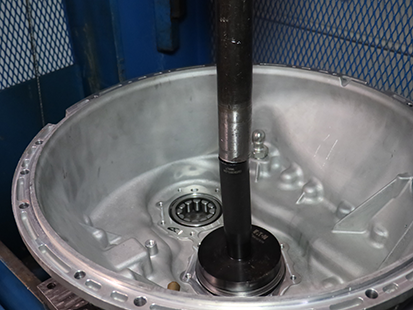
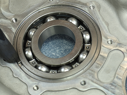
Verify Input Shaft Bearing is fully seated in Clutch Housing.
Place Clutch Housing in press with flywheel housing side of the Clutch Housing down on Input Shaft Stand (RR1073TR), supporting the Inner Bearing Race of the Input Shaft Bearing.
Notice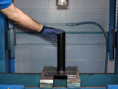
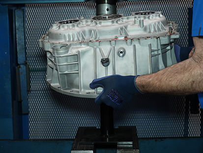
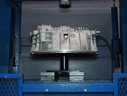
Install Input Shaft into Clutch Housing.
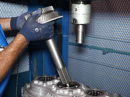
Place Input Shaft Cup (RR1085TR-6) on the Input Shaft.
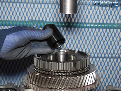
Press Input Shaft into Input Shaft Bearing until fully seated.
Notice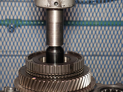
Install Input Shaft Snap Ring.
NoticeNote: The snap ring will not install if Input Shaft is not fully seated into Input Shaft Bearing.
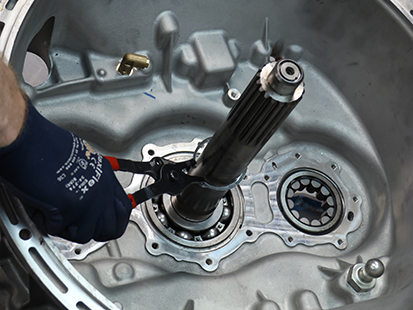
Install Input Shaft Cover
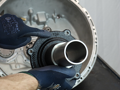
Clean sealing surfaces on the Clutch Housing and Input Shaft Cover.
Slide the Input Shaft Cover over the Input Shaft.
Note: Align "TOP" at 12 o'clock.
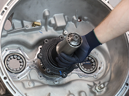
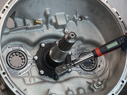
Install the 7 Input Shaft Cover 13 mm cap screws and torque to 21-25 Nm (16-19 lb-ft) in a criss-cross pattern.
Manually Disassemble Input Shaft with Input Shaft Press (RR1085TR)
Ensure Input Shaft Snap Ring is removed.
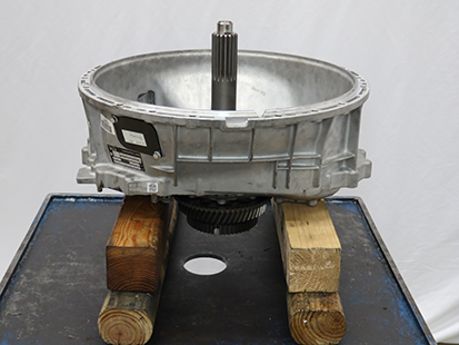
Place and support Clutch Housing on a bench.
Note: Allow space to press the Input Shaft out of Clutch Housing.
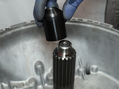
Place Input Shaft Cup (RR1085TR-6) on the end of the Input Shaft.
Place Input Shaft Press (RR1085TR) on the flywheel housing side of the Clutch Housing.
Caution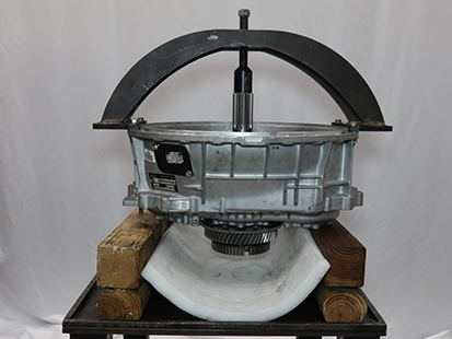
Install and hand tighten 4 (2 inch 7/16 inch Grade 8 or 50.8 mm M12 Grade 10.9) cap screws, washers and nuts to attach press to housing.
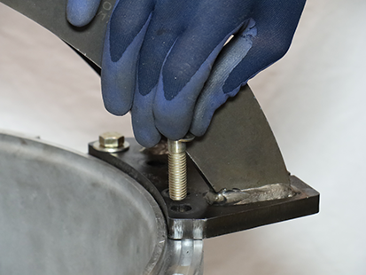
Place soft material under Input Shaft.

Rotate jack screw to press Input Shaft out of Clutch Housing.
Remove 4 cap screws, washers, nuts and Input Shaft Press (RR1085TR) from Clutch Housing.
CautionPlace and support Clutch Housing on a bench.
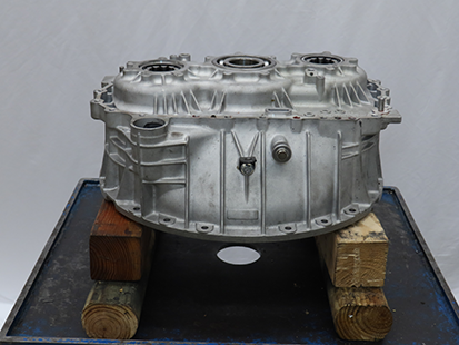
Install Input Shaft Press (RR1085TR) on the Main Housing side of the Clutch Housing aligning the 3 notches on the side of Linear Clutch Actuator opening.
CautionNotice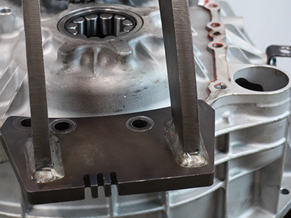
Install and hand tighten 4 Main Housing to Clutch Housing 16 mm cap screws in the inboard holes on each side of the press.
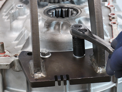
Place Input Shaft Bearing Removal and Installation Tool (RR1075TR) and Input Shaft Cup (RR1085TR-6) onto Input Shaft Bearing.
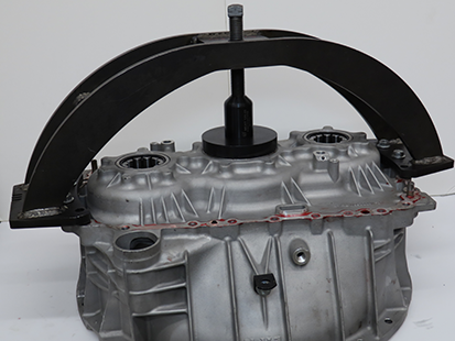
Rotate jack screw to press Input Shaft Bearing out of Clutch Housing.
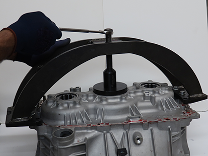
If present, remove Input Shaft Bearing O-ring and discard.
Note: Install a new Input Shaft Bearing O-ring when assembling Clutch Housing with chamfered bearing bores.

Remove 4 cap screws, washers, nuts and Input Shaft Press (RR1085TR) from Clutch Housing.
Caution
Manually Assemble Input Shaft with Input Shaft Press (RR1085TR)
Inspect Input Shaft bearing bore for chamfered edge.
- If chamfer is present, go to Step 2.
- If chamfer is NOT present, go to Step 3.
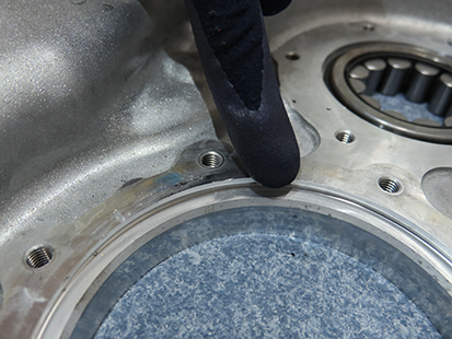
Slide Input Shaft Bearing O-ring on Input Shaft Bearing until fully seated against snap ring.
Note: Install a new Input Shaft Bearing O-ring when assembling Clutch Housing with chamfered bearing bores.


Place Input Shaft Press (RR1085TR) on the flywheel housing side of the Clutch Housing.
CautionInstall and hand tighten 4 (2 inch 7/16 inch Grade 8 or 50.8 mm M12 Grade 10.9) cap screws, washers and nuts to attach press to housing.

Place Input Shaft Bearing into Clutch Housing.
Place Input Shaft Bearing Removal and Installation Tool (RR1075TR), Input Bearing Driver (RR1049TR) and Input Shaft Cup (RR1085TR-6) onto Input Shaft Bearing.
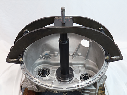
Rotate jack screw to press Input Shaft Bearing into Clutch Housing.
NoticeRemove Input Shaft Bearing Removal and Installation Tool (RR1075TR), Input Bearing Driver (RR1049TR) and Input Shaft Cup (RR1085TR-6).
Verify Input Shaft Bearing is fully seated in Clutch Housing.

Install Front Bearing Capture Plate (RR1085TR-7) to the Clutch Housing using the Input Shaft Cover threaded mounting holes and hand tighten 4 plate cap screws with a 6 mm hex key.
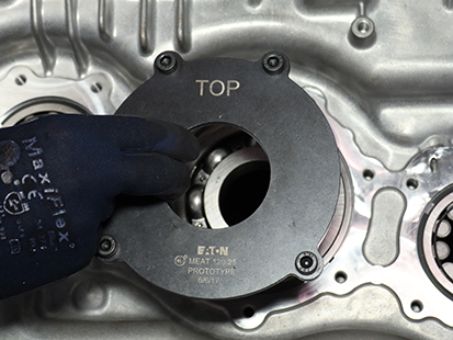
Torque cap screws to 21-25 Nm (16-19 lb-ft) in a criss-cross pattern.
Place and support Clutch Housing on a bench.
Note: Allow space to press the Input Shaft into Clutch Housing.

Install Input Shaft into Clutch Housing.
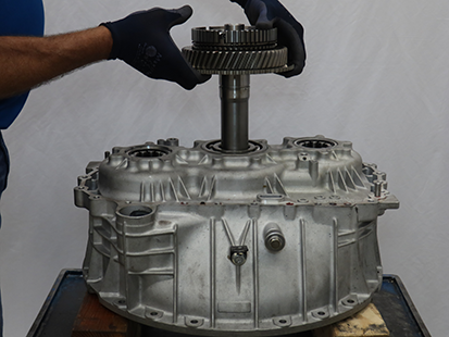
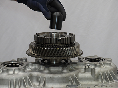
Place Input Shaft Cup (RR1085TR-6) onto Input Shaft.
Install Input Shaft Press (RR1085TR) on the Main Housing side of the Clutch Housing aligning the 3 notches on the side of Linear Clutch Actuator opening.
CautionNotice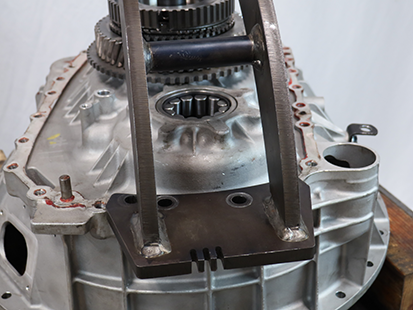
Install and hand tighten 4 Main Housing to Clutch Housing 16 mm cap screws in the inboard holes on each side of the press.

Rotate jack screw to press Input Shaft into Clutch Housing until fully seated.
Notice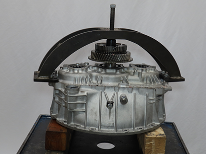
Remove 4 cap screws, washers, nuts and Input Shaft Press (RR1085TR) from Clutch Housing.
Caution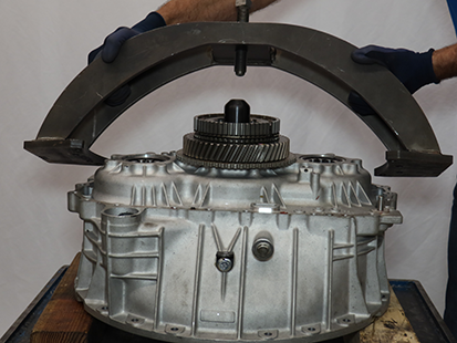
Remove Front Bearing Capture Plate (RR1085TR-7) from Clutch Housing.
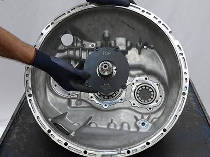
Install Input Shaft Snap Ring.
NoticeNote: The snap ring will not install if Input Shaft is not fully seated into Input Shaft Bearing.

Install Input Shaft Cover
Clean sealing surfaces on the Clutch Housing and Input Shaft Cover.
Slide the Input Shaft Cover over the Input Shaft.
Note: Align "TOP" at 12 o'clock.


Install the 7 Input Shaft Cover 13 mm cap screws and torque to 21-25 Nm (16-19 lb-ft) in a criss-cross pattern.
