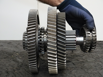
Main Shaft
Special Instructions
Ensure to determine and install the Ideal Main Shaft Selective Washer during Main Shaft Assembly.
Note: The Main Shaft End-Play Service Procedure is required if one or more of the following parts are replaced:
- Clutch Housing
- Main Housing
- Input Shaft
- Input Shaft Bearing
- Main Shaft Bearing
Special Tools
- 5/32 OD Air Line
Component Identification
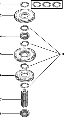 | |
1. Main Shaft Selective Washer - 6.525 mm (0.257 in), 6.712 mm (0.264 in) or 6.900 mm (0.272 in) (x1) 2. Reverse Gear 3. Main Shaft Washer 6.525 mm (0.257 in) (x4) 4. Rail D Sliding Clutch | 5. Primary Driven Gear 6. Secondary Driven Gear 7 Main Shaft Assembly 8. Rail C Sliding Clutch |
Disassemble the Main Shaft
Place Main Shaft Assembly horizontally on a clean flat surface.
CautionRemove Rail C Sliding Clutch.
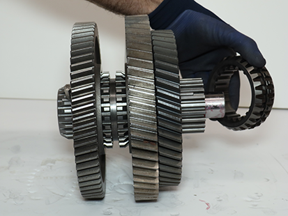
Place Main Shaft assembly vertically on a clean flat surface.
Caution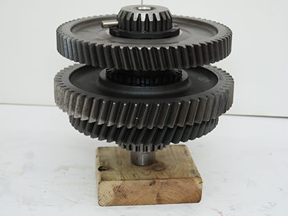
Remove Main Shaft Key.
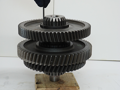
Rotate and remove the Main Shaft Selective Washer above Reverse Gear.
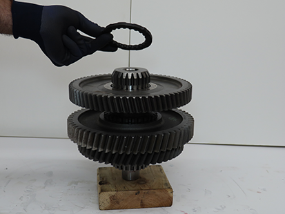
Measure the Main Shaft Selective Washer with a micrometer and record reading in table.
Note: The Main Shaft Selective Washer above Reverse Gear is available in 3 thicknesses, 6.525 mm (0.257 in), 6.712 mm (0.264 in) or 6.900 mm (0.272 in), to control Main Shaft End-Play. The recorded Main Shaft Selective Washer thickness is required for the Main Shaft Assembly Service Procedure. The 4 other Main Shaft Washers are 6.525 mm (0.257 in).
Note: Need image of using micrometer to measure high points on selective washer
Remove Reverse Gear.
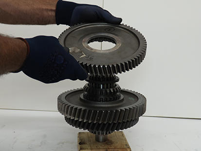
Rotate and remove standard Main Shaft Washer above Rail D Sliding Clutch.
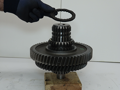
Remove Rail D Sliding Clutch.
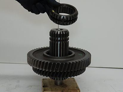
Using magnets, rotate and remove standard Main Shaft Washer above Primary Driven Gear.
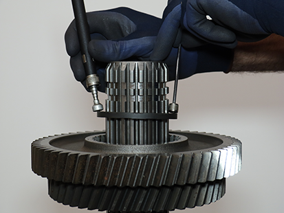
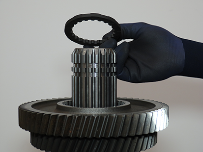
Remove Primary Driven Gear.
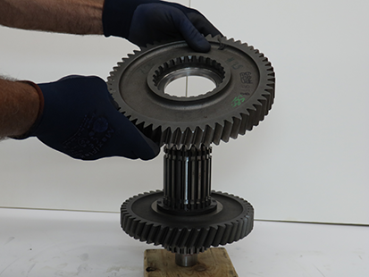
Rotate and remove Main Shaft Washer above Secondary Driven Gear.
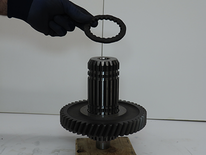
Remove Secondary Driven Gear.
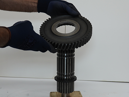
Rotate and remove last Main Shaft Washer.
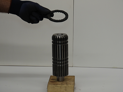
Assemble the Main Shaft
Place Main Shaft vertically on a clean flat surface.
Caution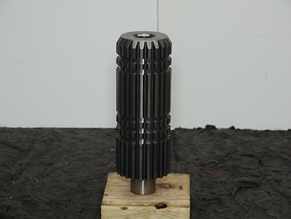
Install and rotate Main Shaft Washer, 6.525 mm (0.257 in), onto Main Shaft.
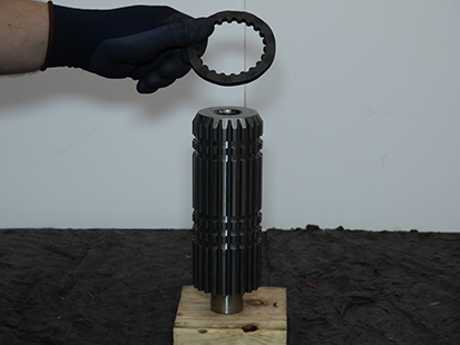
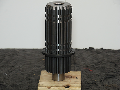
Install a 5/32 OD air line into the main shaft spline to align and hold washer in place.
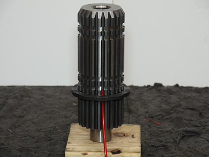
Install Secondary Driven Gear on Main Shaft with clutching teeth facing down.
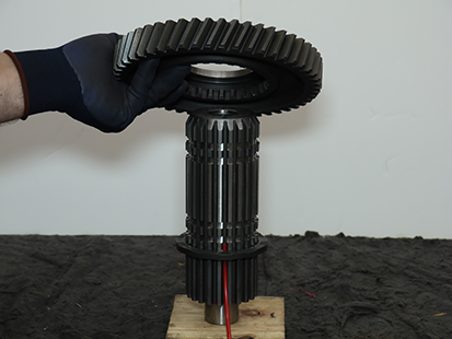
Install and rotate Main Shaft Washer, 6.525 mm (0.257 in), above Secondary Driven Gear.
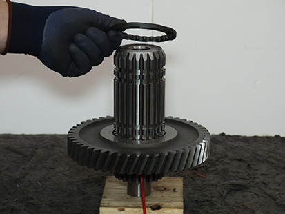
Slide the 5/32 OD air line up to align and hold washer in place.
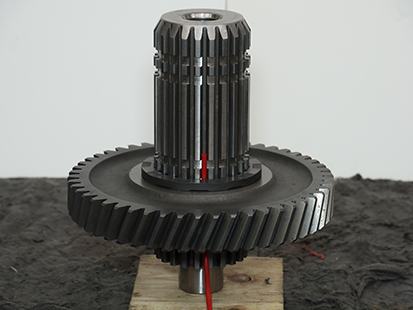
Install Primary Driven Gear on Main Shaft with clutching teeth facing up.
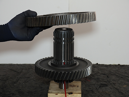
Using magnets, install and rotate Main Shaft Washer, 6.525 mm (0.257 in) above Primary Driven Gear.
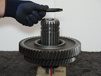
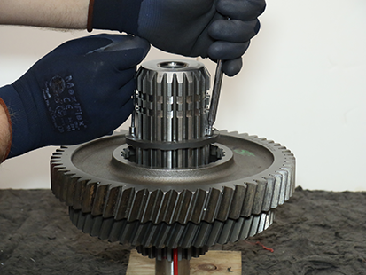
Slide the 5/32 OD air line up to align and hold washer in place.
Install Rail D Sliding Clutch and align the double slot with the 5/32 OD air line.
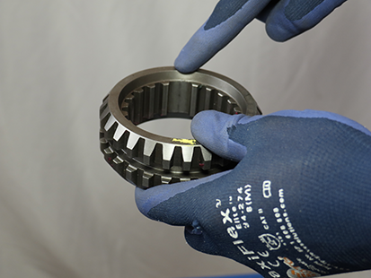
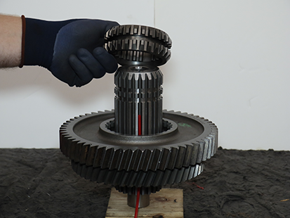
Install and rotate Main Shaft Washer, 6.525 mm (0.257 in), above Rail D Sliding Clutch.
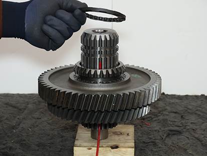
Slide the 5/32 OD air line up to align and hold washer in place.
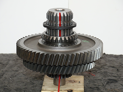
Install Reverse Gear with clutching teeth facing down.
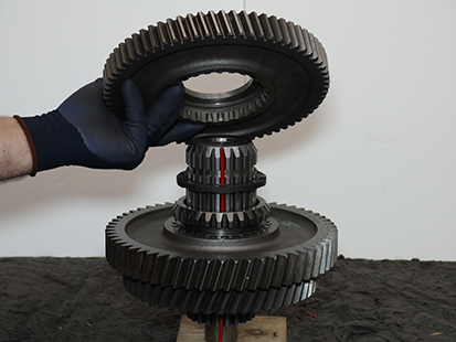
Determine the Ideal Main Shaft Selective Washer to install above Reverse Gear:
Caution- If one or more of the following parts were replaced: Clutch Housing, Main Housing, Input Shaft, Input Shaft Bearing or Main Shaft Bearing, install the 6.525 mm (0.257 in) Main Shaft Selective Washer.
Note: The Main Shaft End-Play Service Procedure is required.
- If NONE of the following parts were replaced: Clutch Housing, Main Housing, Input Shaft, Input Shaft Bearing, or Main Shaft Bearing, install the Main Shaft Selective Washer recorded in Step 6 of the Main Shaft Disassembly Service Procedure: 6.525 mm (0.257 in), 6.712 mm (0.264 in) or 6.900 mm (0.272 in).
Note: The Main Shaft End-play Service Procedure is NOT required.
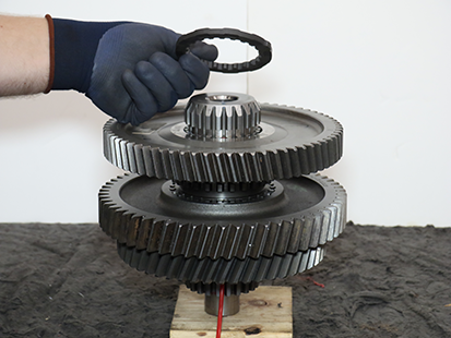
- If one or more of the following parts were replaced: Clutch Housing, Main Housing, Input Shaft, Input Shaft Bearing or Main Shaft Bearing, install the 6.525 mm (0.257 in) Main Shaft Selective Washer.
Slide the 5/32 OD air line up to align and hold washer in place.
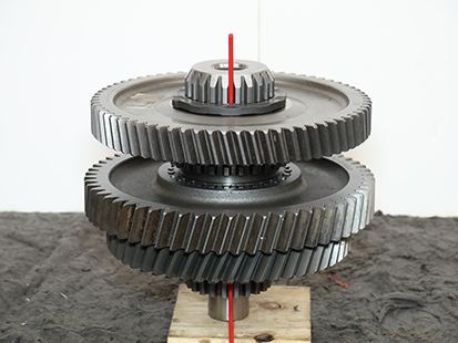
Install Main Shaft Key at the same spline as the 5/32 OD air line.
Note: Insert Main Shaft Key while removing air line.
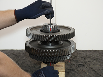
Install a magnet on Main Shaft Key to hold the key in place during final Main Shaft Assembly and installation into transmission.
Note: Remove magnet from Main Shaft Key after installation of Main Shaft Assembly onto transmission.
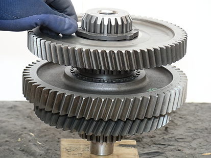
Place Main Shaft Assembly horizontally on a clean flat surface.
CautionInstall Rail C Sliding Clutch and align the double slot with Main Shaft Key.

