Output Speed Sensor
Special Instructions
None
Special Tools
None
Component Identification
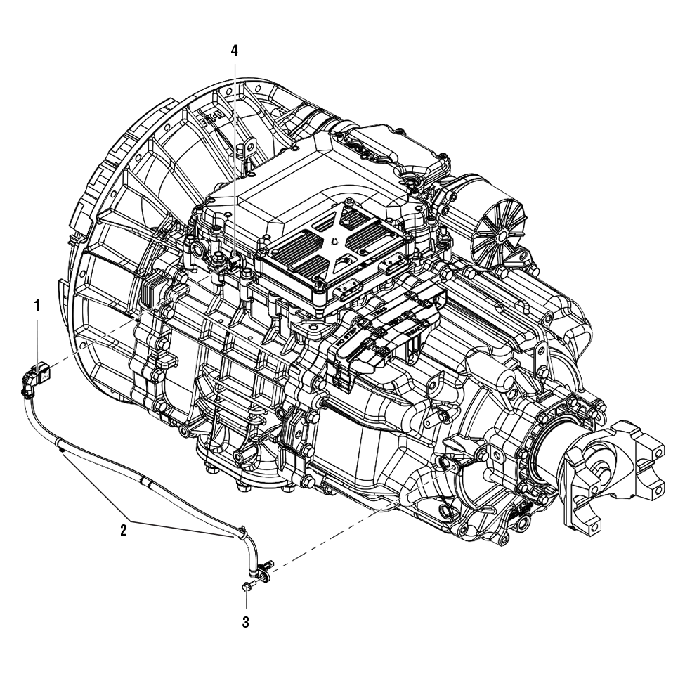 |
1. Output Speed Sensor Harness 2. Harness Retainers (x2) 3. Cap Screw - 10 mm 4. Output Speed Sensor Connector |
Create a Service Activity Report
Note: If not already created and sent.
Key on with engine off.
Connect ServiceRanger and create a Service Activity Report.
Select “Send to Eaton” (internet connection required)
Disconnect ServiceRanger.
Key off.
Disconnect the Output Speed Sensor
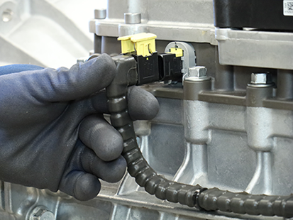
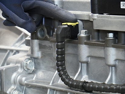
Lift the latch on the Output Speed Sensor Harness at the Connector on the Mechatronic Transmission Module (MTM).
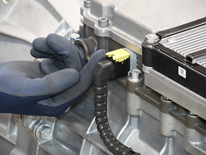
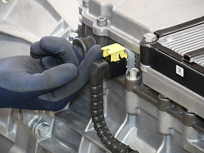
Remove the Output Speed Sensor Harness from the Connector on the MTM.
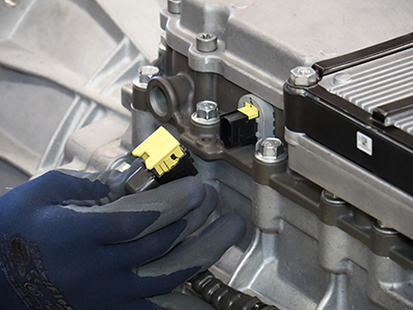
Remove the Output Speed Sensor
Remove the Output Speed Sensor Harness tie strap at the Harness Bracket.
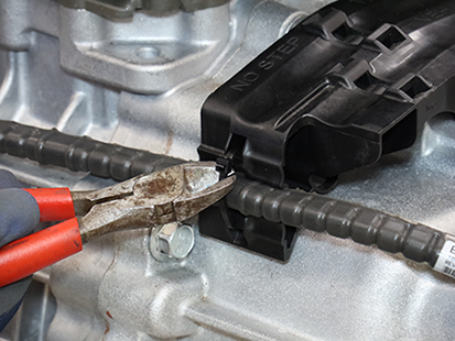
Remove the 2 harness press-in retainers from the Main Housing and bracket on Rear Housing.
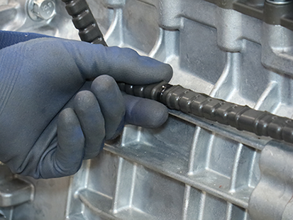
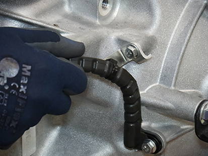
Remove the Output Speed Sensor 10 mm cap screw.
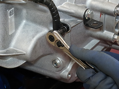
Remove the Output Speed Sensor from the Rear Housing.
Note: The sensor may need to be twisted and pulled from the bore.
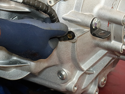
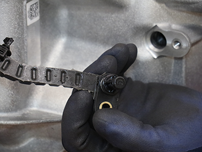
Install the Output Speed Sensor
Clean the sensor bore.
NoticeApply a light coat of transmission oil to the sensor O-ring.
Install the Output Speed Sensor into the bore.
Note: The Sensor may need to be twisted and pushed into the bore.
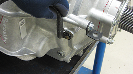
Install the Output Speed Sensor 10 mm cap screw and torque to 8.8-10.4 Nm (6-8 lb-ft).
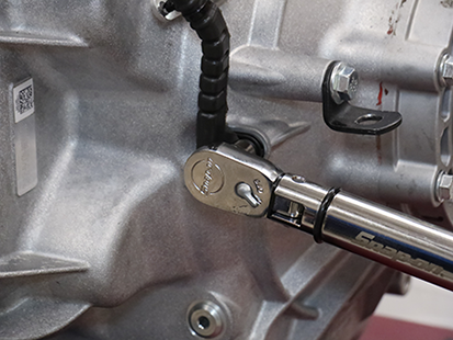
Press the 2 harness press-in retainers into the Main Housing and the bracket on the rear housing.
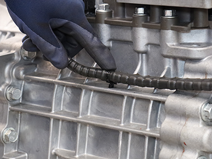
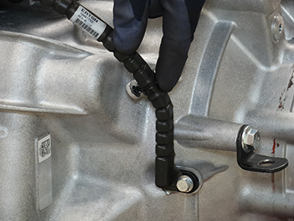
Secure the Output Speed Sensor Harness to the Harness Bracket with a tie strap.
Caution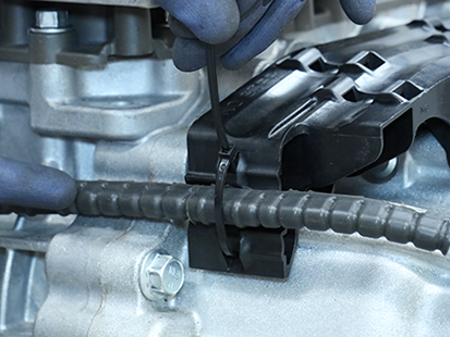
Connect the Output Speed Sensor
Connect the Output Speed Sensor Harness to the Connector on the Mechatronic Transmission Module (MTM) and close the latch.
