RRMT0027 - Clutch Housing Front Cover Kit
Special Instructions
K-4491 should be installed on transmissions built prior to July 29th, 2019 serial number Z0123456 whenever a transmission is removed. Contact the Roadranger Call Center at 1-800-826-4357 for warranty guidelines. K-4491 will be added to new production transmissions targeted to be built 07/19/2021.
Special Tools
- ServiceRanger
- Transmission Assembly Lube (Lubegard® Assemblee Goo Firm Tack - Green #19250 or equivalent)Notice
- Non-Chlorinated Brake CleanerDangerCaution
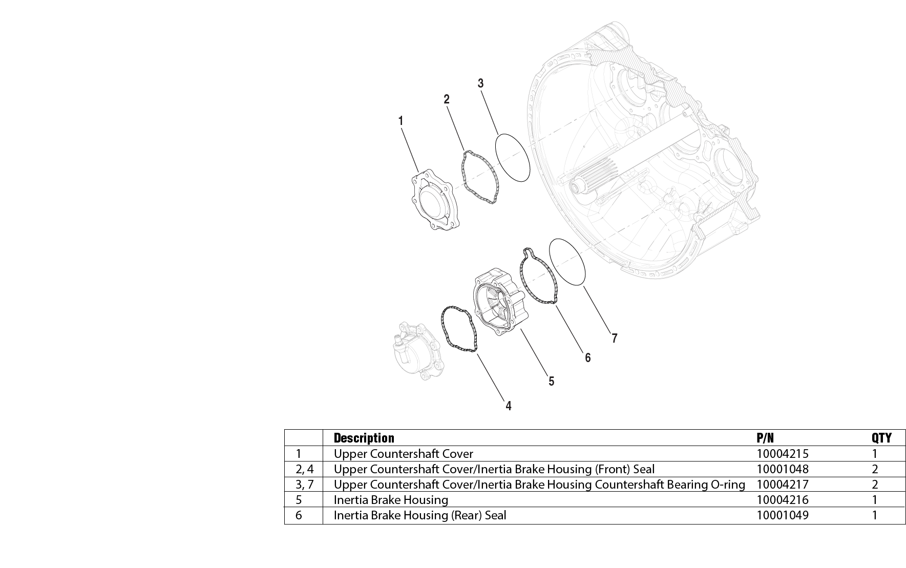
Component Identification
 |
Manually Vent Linear Clutch Actuator (LCA)
Key off.
Set vehicle parking brake and chock wheels.
WarningLoosen the 4 Linear Clutch Actuator (LCA) cap screws 1-2 turns each with a T45 Torx.
Note: Residual air pressure in the LCA cylinder exhausts between the LCA and Mechatronic Transmission Module (MTM) housing when the cap screws are loosened.
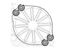
Tighten the 4 LCA to MTM T45 cap screws and torque to 23-27 Nm (17-21 lb-ft).
Drain Oil
Locate the Oil Drain Plug on the back of the rear housing.
Place a suitable container under the Oil Drain Plug.
Note: Original oil is not to be reused.
Remove the Oil Drain Plug with a 6 mm hex key and drain the oil.
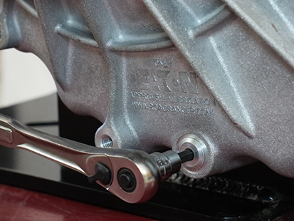
Inspect Oil Drain Plug and O-ring for damage. If damaged, replace the Oil Drain Plug; O-ring is serviced with plug.
Install the Oil Drain Plug (6 mm) and torque to 24.5-29.5 Nm (18-22 lb-ft).
Notice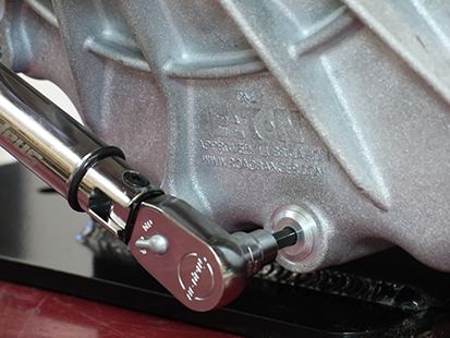
Remove Transmission
Disconnect negative battery cable.
Refer to OEM guidelines for transmission removal.
Remove Release Bearing and Clutch Release Yoke
Remove the Release Bearing by sliding the bearing off the Input Shaft Cover.
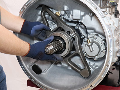
Pull to free the lower Clutch Release Yoke socket from the lower pivot on the clutch housing.
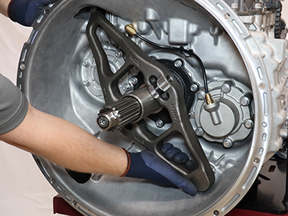
Pull to free the upper Clutch Release Yoke socket from the Linear Clutch Actuator (LCA) rod end.
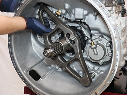
Remove Upper Countershaft Cover
Remove the 6 Upper Countershaft Cover 13 mm cap screws and remove cover.The original Upper Countershaft Cover and Front Seal are not to be reused.
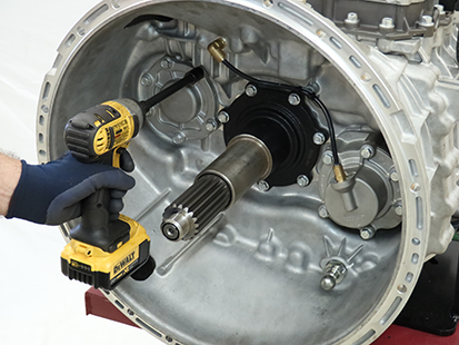
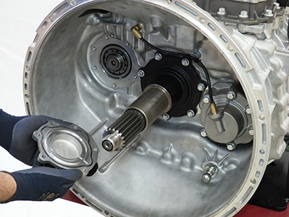
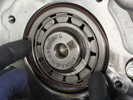
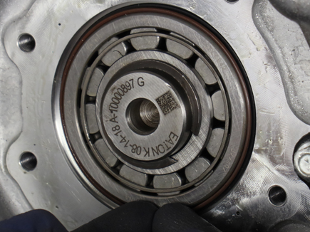
Install Upper Countershaft Cover Countershaft Bearing O-ring
Clean any residual oil from the Upper Countershaft Bearing outer diameter using Non-Chlorinated Brake Cleaner.
Install the Upper Countershaft Cover Countershaft Bearing O-ring (10004217) onto the Upper Counter- shaft Bearing.
Note: O-ring may fall out of position after installation. Ensure to clean any residual oil from the bearing and roll the O-ring on to the bearing using the tips of your fingers pushing on the inner diameter of the O-ring. If necessary, apply a small amount of transmission assembly lube at the 3, 6, 9 and 12 o'clock positions to the outer diameter of the bearing.
Install Upper Countershaft Cover
Clean the sealing surfaces on the clutch housing and the new Upper Countershaft Cover.
Note: The new Upper Countershaft Cover has a chamfer that is required for the bearing O-ring.
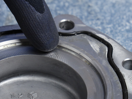
Install new Countershaft Cover front seal (10001048) into the groove of the new Upper Countershaft Cover (10004215) until fully seated
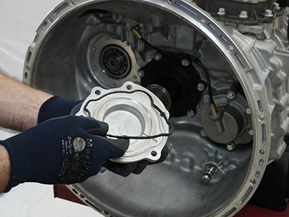
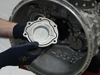
Install the new Upper Countershaft Cover and six 13 mm cap screws to the clutch housing and torque to 21-25 Nm (16-19 lb-ft) in a criss-cross pattern.
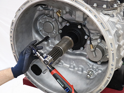
Remove Lower Countershaft Cover and Inertia Brake
Depress and hold collar on air line fitting and disconnect the air line from the Inertia Brake Cover.
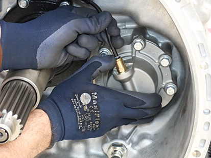
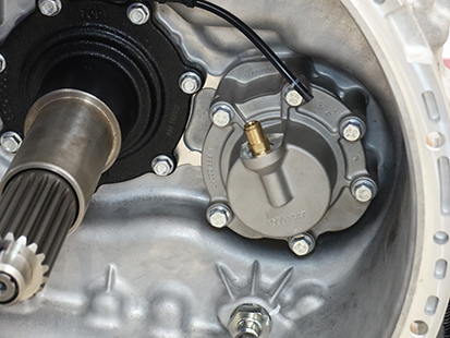
Remove the 6 Inertia Brake Cover 13 mm cap screws.
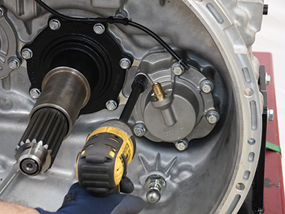
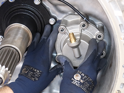
Remove the Inertia Brake Cover and Housing as an assembly. The original Inertia Brake Housing and seals are not to be reused.
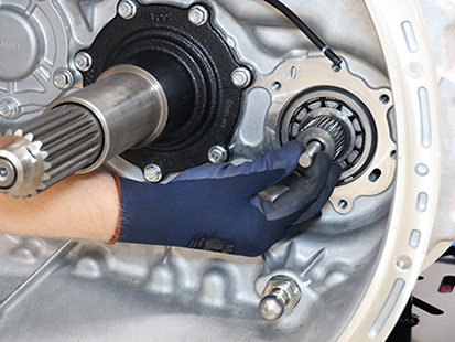
Ensure the Inertia Brake Piston Pin and Return Spring remain in the Lower Countershaft.
Disassemble Inertia Brake
Remove the clutch pack from the Inertia Brake Housing.
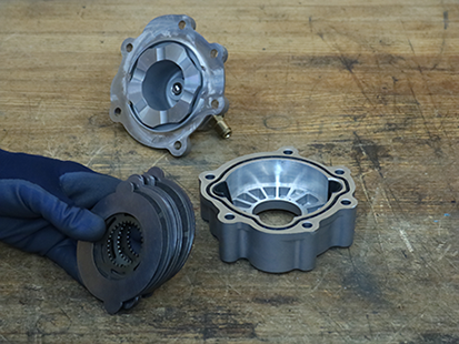
Remove the 2 wear guides from the Inertia Brake Housing.
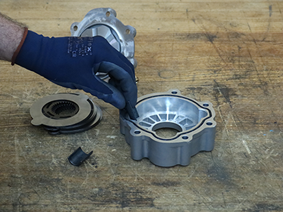
Assemble Inertia Brake
Clean sealing surfaces on the clutch housing and the new Inertia Brake Housing.
Note: The new Inertia Brake Housing (10004216) has a chamfer on the Clutch Housing side that is required for the bearing O-ring.
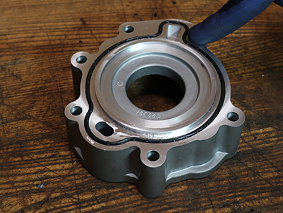
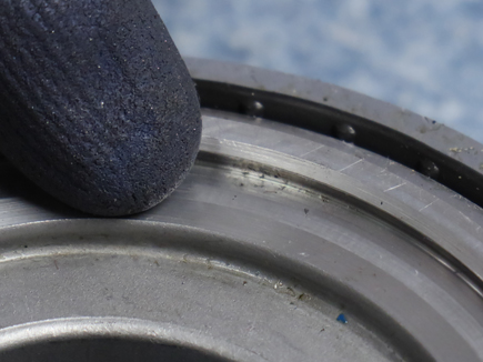
Insert the new Inertia Brake Rear Seal (10001049) into the groove on the rear of the new Inertia Brake Housing (10004216) until fully seated.
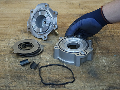
Insert the new Inertia Brake Housing Front Seal (10001048) into the new Inertia Brake Housing (10004216) until fully seated.
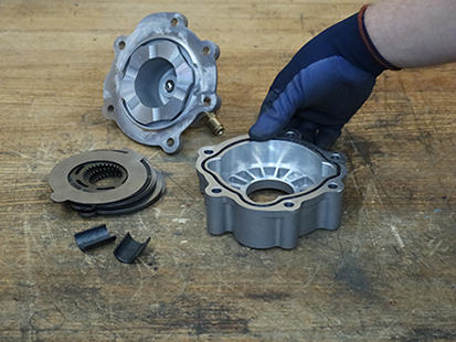
Install the 2 original Wear Guides into the new Inertia Brake Housing (10004216).
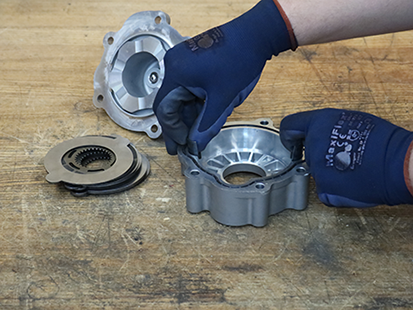
Install the original inertia brake clutch pack in the order shown below:
- 1 Steel Disc,
- 1 Friction Disc,
- 2 Steel Discs,
- 1 Friction Disc,
- 2 Steel Discs,
- 1 Friction Disc, and
- 1 Steel Disc.
Note: Steel Discs align with Wear Guides. Friction Discs spline to the lower countershaft.

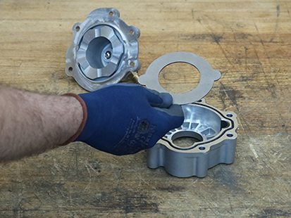
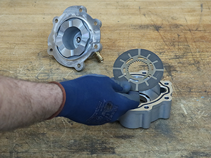
Place Inertia Brake Cover and Piston on the Housing. Align the bolt holes.
Install Inertia Brake Housing Countershaft Bearing O-ring
Clean any residual oil from the Lower Countershaft Bearing outer diameter using Non-Chlorinated Brake Cleaner.
Install the Inertia Brake Housing Countershaft Bearing O-ring (10004217) onto the Lower Countershaft Bearing.
Note: O-ring may fall out of position after installation. Ensure to clean any residual oil from the bearing and roll the O-ring on to the bearing using the tips of your fingers pushing on the inner diameter of the O-ring. If necessary, apply a small amount of transmission assembly lube at the 3, 6, 9 and 12 o'clock positions to the outer diameter of the bearing.
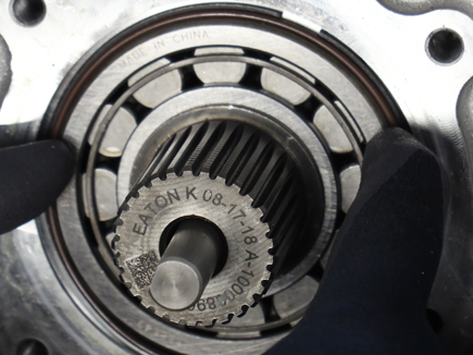
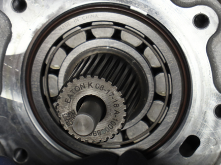
Install Inertia Brake Cover and Housing
Install the Inertia Brake Cover and the new Housing as an assembly over the Lower Countershaft, rotate the assembly to align the Friction Discs to the Lower Countershaft splines and seat the assembly to the clutch housing.

While holding the Inertia Brake Housing to the clutch housing, remove the Inertia Brake Cover.
Notice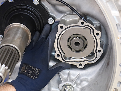
If removed, install the Return Spring into the Lower Countershaft.
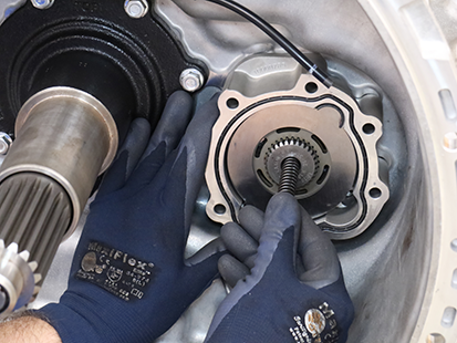
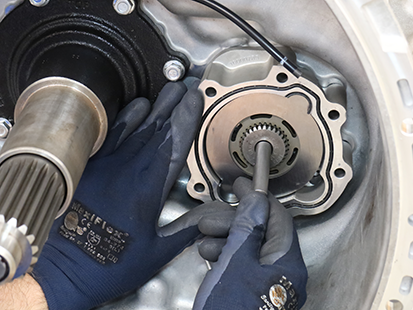
If removed, install the Piston Pin into the Lower Countershaft.
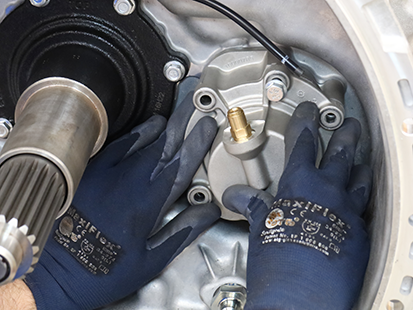
Install the Inertia Brake Cover onto the housing.
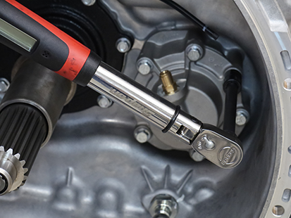
Install the six 13 mm cap screws and torque to 21-25 Nm (16-19 lb-ft) in a criss-cross pattern.
Insert air line in push-to-connect fitting on the Inertia Brake Cover.
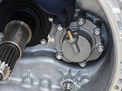
Remove the Linear Clutch Actuator (LCA)
Loosen the 4 LCA cap screws 1-2 turns each with a T45 Torx.
NoticeNote: Residual air pressure in the LCA cylinder exhausts between the LCA and MTM housing when the cap screws are loosened.
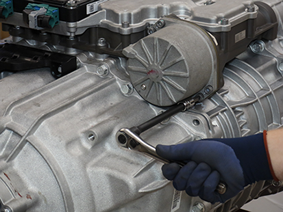
Remove the 4 LCA cap screws
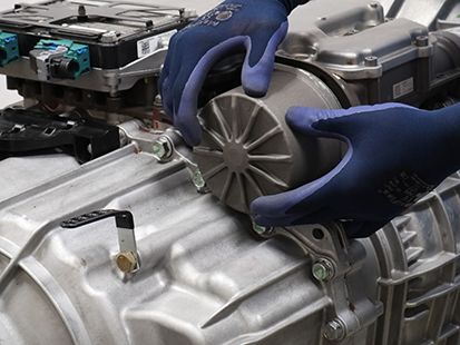
Remove the LCA from the MTM.
Note: LCA piston rod end is seated in the release yoke socket; pull to release rod end from socket.
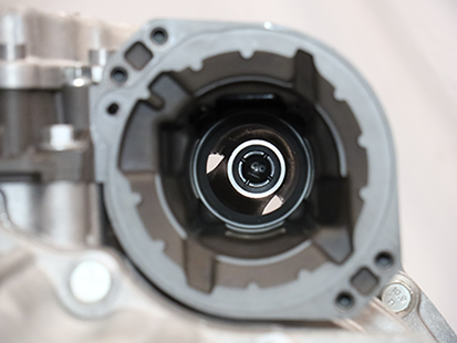
Inspect the plastic socket insert in the release yoke through the LCA opening using a flashlight to verify none of the fingers are missing or damaged.
Note: If the plastic insert is damaged, replace the release yoke assembly.
Reset and Install Linear Clutch Actuator (LCA)
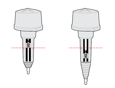
Inspect LCA to determine next steps, reference images below:
- If LCA is locked in the reset position, go to Install Linear Clutch Actuator (LCA).
- If LCA is not locked in the reset position, go to Step 2.
Locked in Reset Position
Not Locked in Reset Position
Place LCA push rod on a clean, flat surface. Tightly grasp LCA housing with both hands and push down on push rod to lock LCA into the reset position.
Caution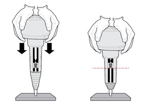
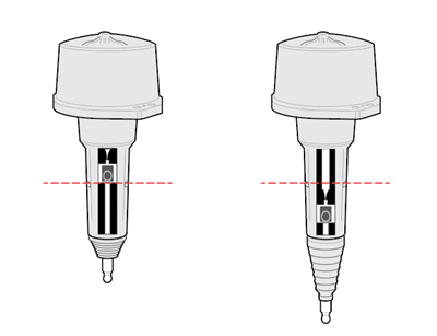
Inspect LCA to determine next steps, reference images below:
- If LCA remains locked in the reset position, go to Step 4.
- If LCA does not remain locked in the reset position, go to Step 2, repeat reset procedure.
Note: If LCA cannot be locked into the reset position, replace LCA.
CautionLocked in Reset Position
Not Locked in Reset Position
Clean all sealing surfaces on the MTM and LCA with a lint free cloth.
NoticeInsert the LCA into the MTM.
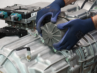
Install 4 LCA T45 cap screws and torque to 23-28 Nm (17-21 lb-ft) in a criss-cross pattern.
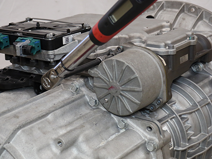
Install the Release Bearing and Clutch Release Yoke
Install the upper Release Yoke socket over the rod end of the Linear Clutch Actuator (LCA) and press until attached.

Install the lower Release Yoke socket over the lower pivot on the clutch housing and press until attached.
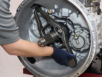
Slide the Release Bearing over the input shaft and into the Release Yoke.

Install Transmission
Refer to OEM guidelines for transmission installation.
Connect negative battery cable.
Fill Oil
Remove the Oil Fill Plug with a 6 mm hex key.
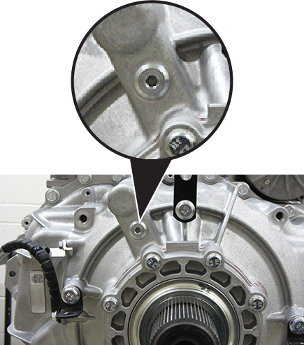
Place a suitable container under the Oil Check Plug and remove the Oil Check Plug with a 6 mm hex key.
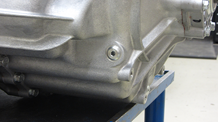
Fill the transmission with PS-386 lube until a small amount of oil runs out of the Oil Check Plug hole.
Note: Fill capacity is approximately 7.5-8.5 liters (16-18 pints) depending on the transmission angle.
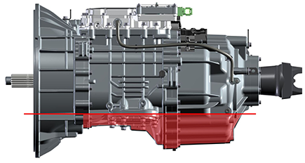
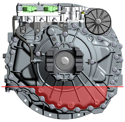
Inspect Oil Check Plug and O-ring for damage. If damaged, replace the Oil Check Plug; O-ring is serviced with plug.
Install the Oil Check Plug (6 mm) and torque to 24.5-29.5 Nm (18-22 lb-ft).
Notice
Inspect Oil Fill Plug and O-ring for damage. If damaged, replace the Oil Fill Plug; O-ring is serviced with plug.
Install the Oil Fill Plug (6 mm) and torque to 24.5-29.5 Nm (18-22 lb-ft).
Notice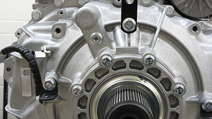
Clutch and Rail Calibration
To ensure proper operation, the TCM, clutch, MTM and transmission require a Clutch and Rail Calibration. Calibrations are automatically initiated when:
- LCA is in the reset position
- Transmission in “N” (Neutral)
- Key on engine running
- Vehicle air system pressure at operating range
Note: Vehicle display may indicate a flashing “CC” and “F” in gear display.
Set vehicle parking brake and chock wheels.
Ensure the driveline is connected between the transmission and axle.
Note: Clutch and Rail Calibrations cannot complete if the transmission output shaft is allowed to rotate.
Key on with engine running.
Allow vehicle air pressure to build to governor cut-off.
Note: Clutch and Rail Calibrations automatically initiate when vehicle air pressure reaches approximately 100 psi.
Ensure “N” (Neutral) is selected and engine is running. Wait approximately 2 minutes for calibrations to complete.
Notice- If vehicle display indicates a solid “N: (Neutral) in gear display, calibrations are complete. Key off, go to Step 6.
- If vehicle display continues to indicate a flashing “CC” and/or “F” in gear display or service transmission message, go to Step 5.
Key off and wait 1 minute.
Key on with engine off.
Connect ServiceRanger.
Go to “Fault Codes”.
- If an Active transmission fault code is set, go to Endurant HD Troubleshooting Guide TRTS0950 Diagnostic Procedure.
- If no Active transmission fault codes are set, select “Clear Eaton Faults” and follow on-screen prompts. Go to Step 9.
Disconnect ServiceRanger.
Key off.
Inspect transmission for a PTO.
- If not PTO-equipped, process complete.
- If PTO-equipped, start the engine and run for 1 to 2 minutes to fill the PTO with oil, key off and repeat the Fill Oil Procedure.
Caution