MTM Rail B, C and D Cover Cap Screw
Special Instructions
- Perform this entire procedure only:
- If guided here by MTM Rail B, C and D Cylinder Inspection Procedure.
- If guided here by TAIB-0994 - MTM was removed for another transmission related issue and MTM Serial Number is less that 12S22342093445.
- Reference the relevant warranty information provided in service bulletin TAIB-0994.
Special Tools
- T30 Torx Bit
- Torque Wrench - Nm (in lbs.)
- Parts Cleaner (Loctite SF 7063 or equivalent)
- Thread Lock (Loctite® 262™ Threadlocker Red or equivalent)Caution
Component Identification
MTM, Fore view 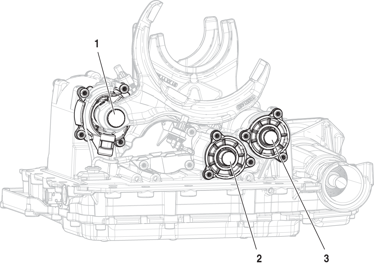 | MTM, Aft view 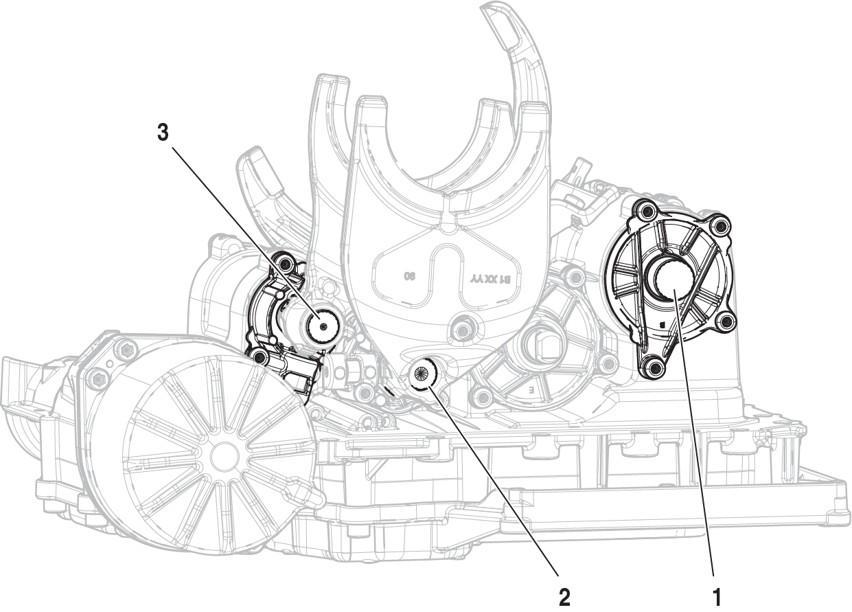 |
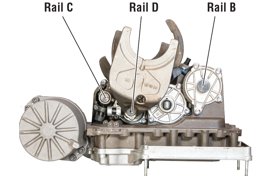
1. MTM Rail B 2. MTM Rail D 3. MTM Rail C | |
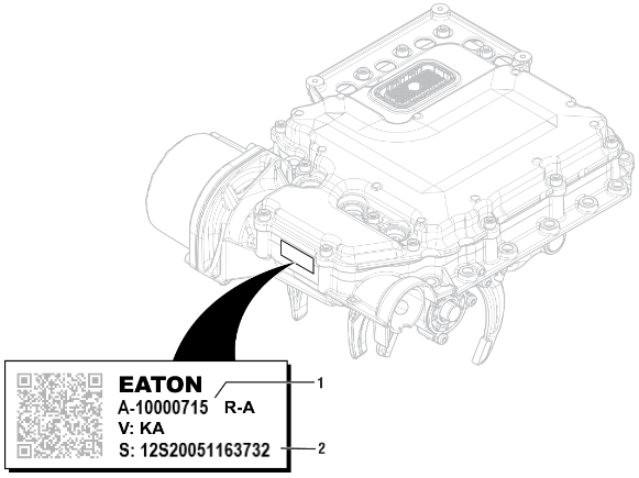 | |
1. Part Number 2. Serial Number |
Procedure - Rail B
Place MTM on a clean surface.
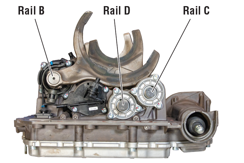
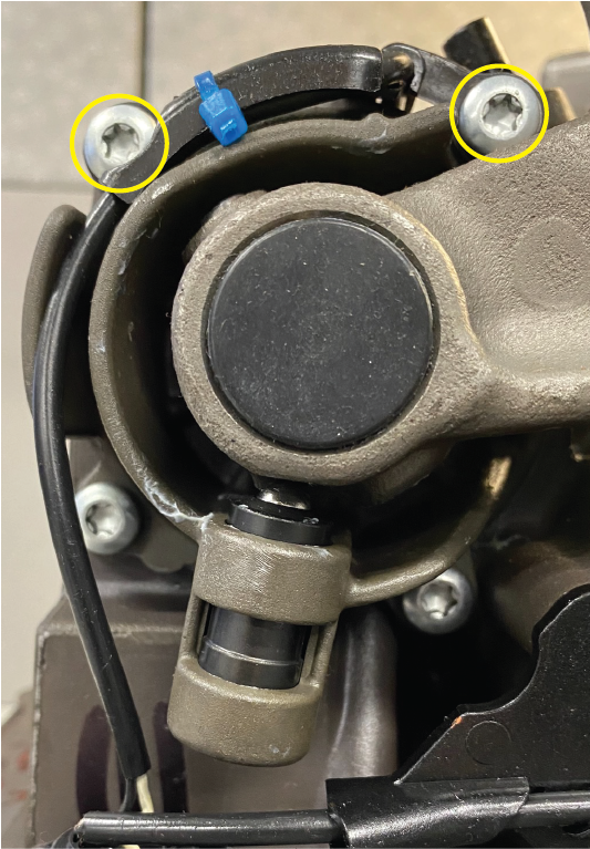
Remove 2 Rail B Shift Yoke Cylinder Cover T30 cap screws (1, 2 - M6x65).
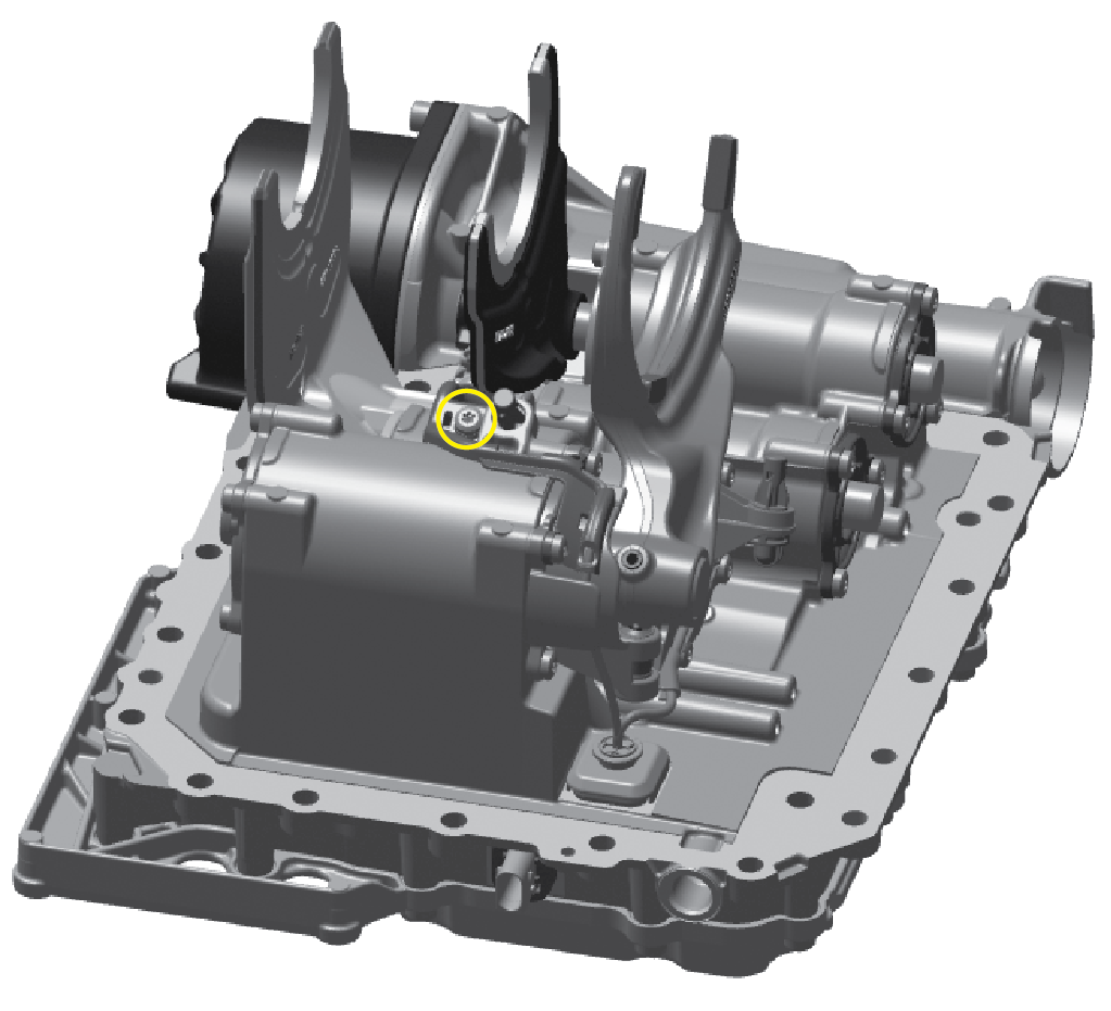
Remove 1 Countershaft Speed Sensor T30 cap screw (5 - M6x65).
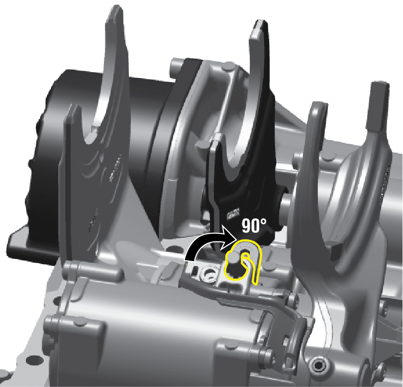
Rotate Countershaft Speed Sensor clockwise 90 degrees.
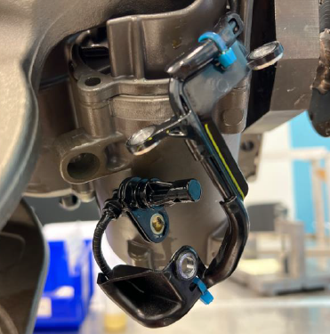
Remove Countershaft Speed Sensor from housing.
Clean Rail B Shift Yoke Cylinder Cover threaded holes with parts cleaner.
NoticeClean Countershaft Speed Sensor threaded hole with parts cleaner.
NoticeInstall Countershaft Speed Sensor.
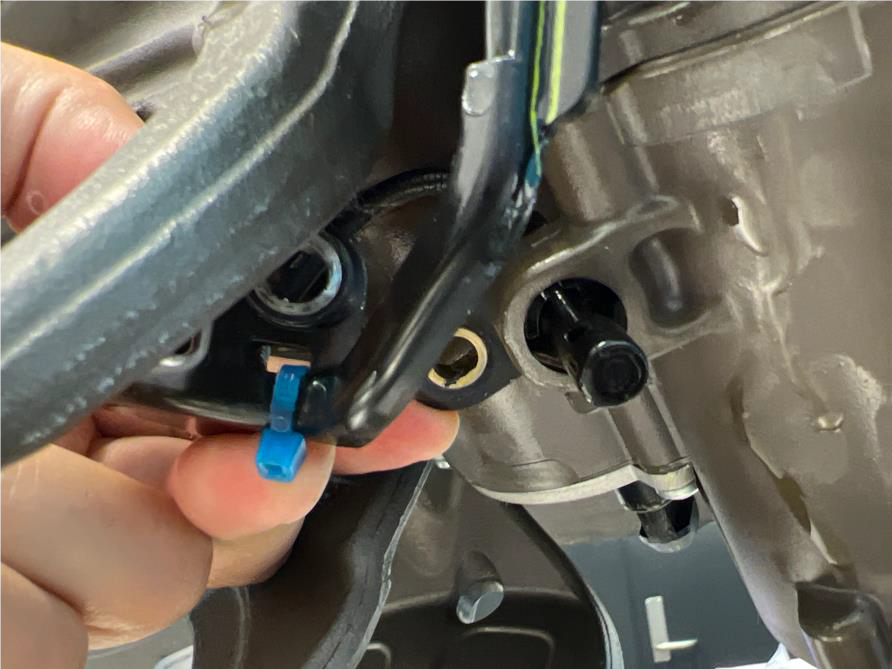
Install Countershaft Speed Sensor harness.
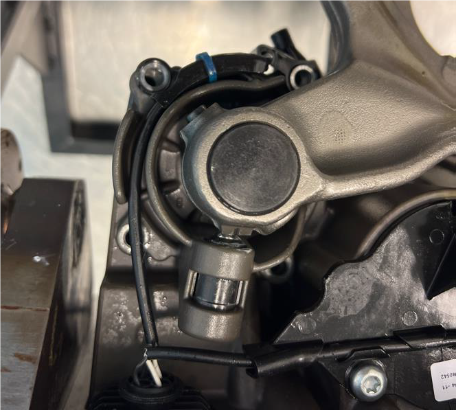
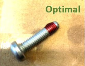
Clean 2 Rail B Shift Yoke Cylinder Cover T30 cap screws (M6x25) with parts cleaner.
Apply thread lock as indicated.
Install 2 Rail B Shift Yoke Cylinder Cover T30 cap screws (1, 2 - M6x25).
Torque cap screws (1, 2) to 9.5-10.5 Nm (84-92 in lbs.).

Clean 1 Countershaft Speed Sensor T30 cap screws (M625) with parts cleaner.
Apply thread lock as indicated.

Install 1 (5) Countershaft Speed Sensor T30 cap screws (M6x25).
Torque to 9.5-10.5 Nm (84-92 in lbs.).

Remove 2 Rail B Shift Yoke Cylinder Cover T30 cap screws (3, 4 - M6x65).
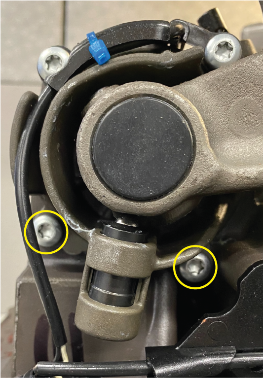
Clean Rail B Shift Yoke Cylinder Cover threaded holes with parts cleaner.
NoticeClean 2 Rail B Shift Yoke Sylinder Cover T30 cap screws (M6x25) with parts cleaner.
Apply thread lock as indicated.

Install 2 Rail B Shift Yoke Cylinder Cover T30 cap screws (3, 4 - M6x25).
Torque cap screws (3, 4) to 11-12 Nm (97-106 in lbs.).

Remove 4 Rail B Cylinder Cover T30 cap screws (M6x65).
Note: Remove, clean, apply thread lock and reinstall one cap screw at a time.
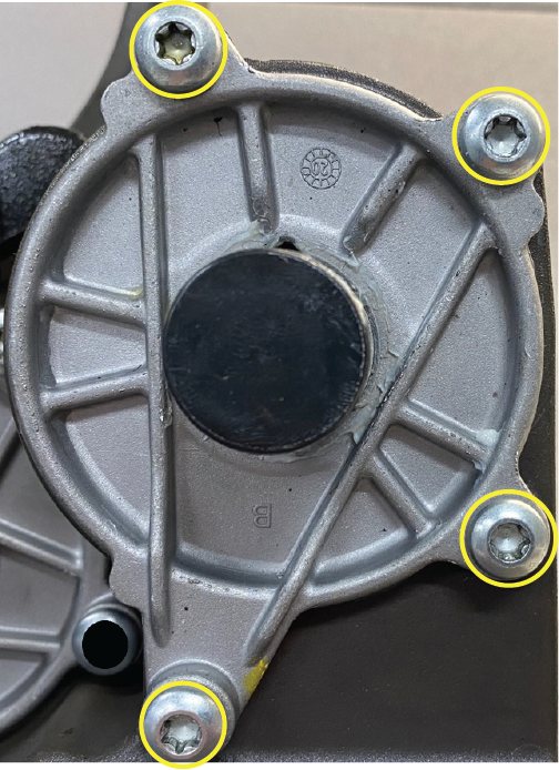
Clean Rail B Cylinder Cover threaded holes with parts cleaner.
NoticeClean 4 Rail B Cylinder Cover T30 cap screws (M6x25) with parts cleaner.
Apply thread lock as indicated.

Install 4 Rail B Cylinder Cover T30 cap screws (M6x25).
Torque to 11-12 Nm (97-106 in lbs.).

Procedure - Rail C
Remove 2 Rail C Shift Yoke Cylinder Cover T30 cap screws (M6x25)
Note: Remove, clean, apply thread lock and reinstall one cap screw at a time.
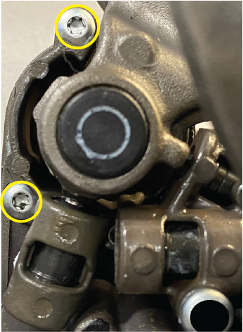

Clean Rail C Cylinder Cover threaded holes with parts cleaner.
NoticeClean 2 Rail C Shift Yoke Cylinder Cover T30 cap screws (M6x25) with parts cleaner.
Apply thread lock as indicated.

Install 2 Rail C Shift Yoke Cylinder Cover T30 cap screws.
Torque to 11-12 Nm (97-106 in lbs.).


Remove 3 Rail C Cylinder Cover T30 cap screws (M6x65).
Note: Remove, clean, apply thread lock and reinstall one cap screw at a time.
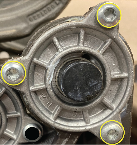
Clean Rail C Cylinder Cover threaded holes with parts cleaner.
NoticeClean 3 Rail C Cylinder Cover T30 cap screws (M6x25) with parts cleaner.
Apply thread lock as indicated.

Install 3 Rail C Cylinder Cover T30 cap screws.
Torque to 11-12 Nm (97-106 in lbs.).

Procedure - Rail D
Move Shift Rails C and D in the MTM to neutral. Rails C and D are in neutral when the shift inter-lock is aligned with the notches of the rail yoke assemblies.

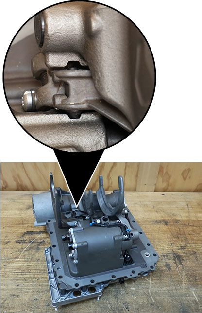
Remove 3 Rail D Shift Yoke Cylinder Cover T30 cap screws (1 - M6x65, 2, 3 - M6x25).
Note: Remove, clean, apply thread lock and reinstall one cap screw at a time.
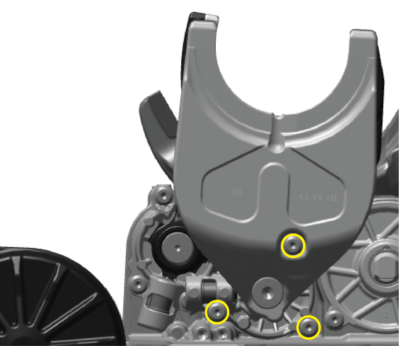
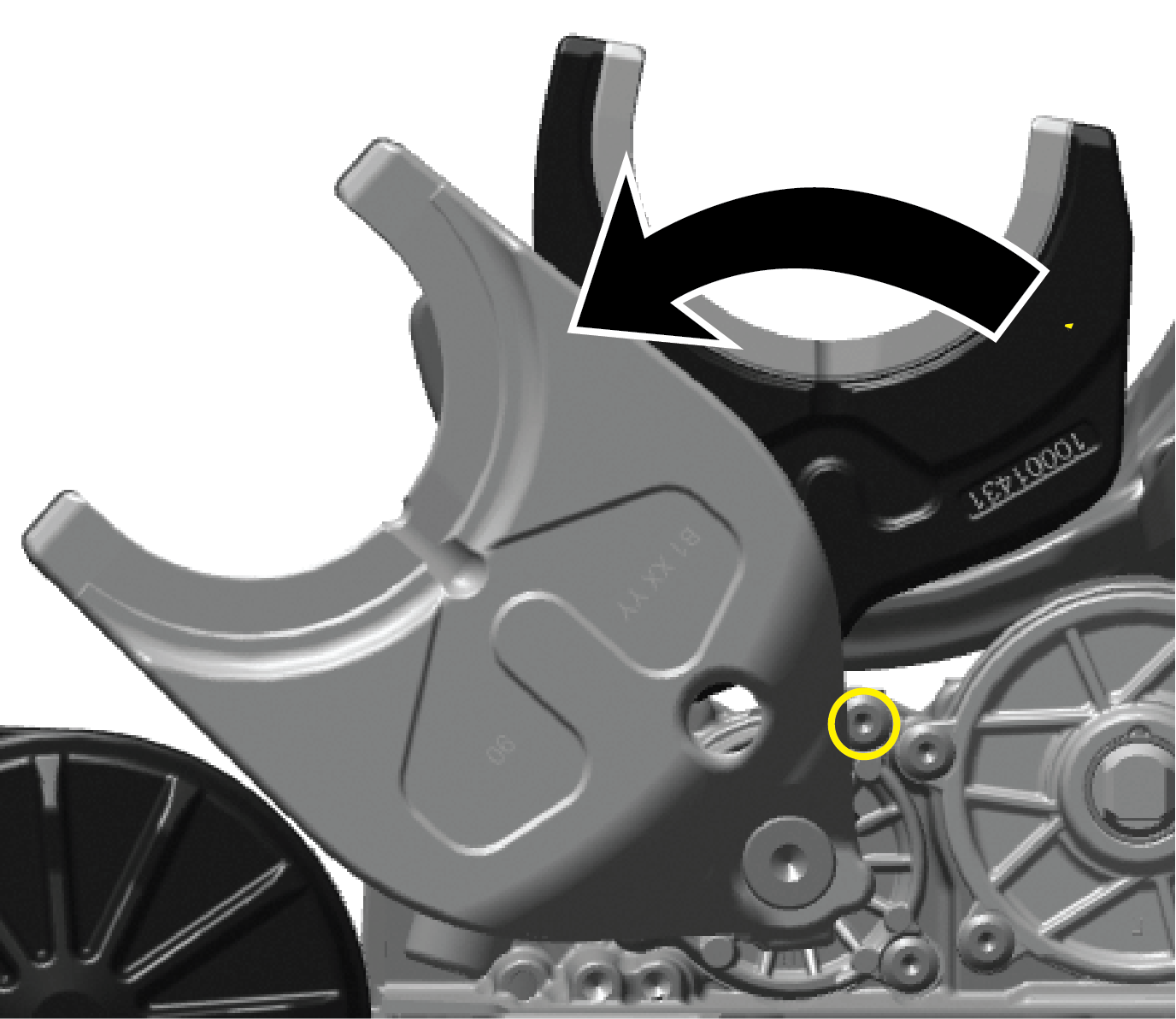
Clean Rail D Shift Yoke Cylinder Cover threaded holes with parts cleaner.
NoticeClean 3 Rail D Shift Yoke Cylinder Cover T30 cap screws (1 - M6x65, 2, 3 - M6x25) with parts cleaner.
Apply thread lock as indicated.

Install 3 Rail D Shift Yoke Cylinder Cover T30 cap screws (1 - M6x65, 2, 3 - M6x25).
Torque to 11-12 Nm (97-106 in lbs.).


Remove 3 Rail D Cylinder Cover T30 cap screws (M6x65).
Note: Remove, clean, apply thread lock and reinstall one cap screw at a time.
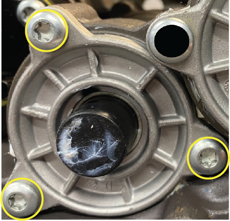
Clean Rail D Cylinder Cover threaded holes with parts cleaner.
NoticeClean 3 Rail D Cylinder Cover T30 cap screws (M6x25) with parts cleaner.
Apply thread lock as indicated.

Install 3 Rail D Cylinder Cover T30 cap screws.
Torque to 11-12 Nm (97-106 in lbs.).

Determine next step.
- If guided here by MTM Rail B, C and D Cylinder Inspection Procedure due to Fault Code 617, 740, 760, 775:
- If Fault Code 617, go to Procedure A.
- If Fault Code 740, go to Procedure B.
- If Fault Code 760, go to Procedure C.
- If Fault Code 775, go to Procedure D.
- If guided here by MTM Rail B, C and D Cylinder Inspection Procedure and no fault codes were originally set, process complete.
- If guided here by TAIB-0994 - MTM was removed for another transmission related issue, process complete.
- If guided here by MTM Rail B, C and D Cylinder Inspection Procedure due to Fault Code 617, 740, 760, 775:
Procedure A
STEP A
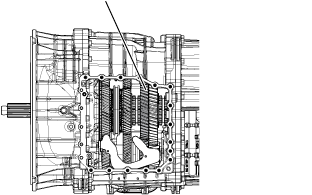
Purpose: Verify mechanical condition of the Secondary Driven Gear
Inspect the Secondary Driven Gear for excessive for and aft movement.
- If excessive gear movement is evident, inspect the Main Shaft Assembly and Secondary Driven Gear and repair. Go to Step V.
- If no excessive gear movement is evident, go to Procedure A, Step B.
Procedure A
STEP B
Purpose: Verify mechanical condition of the Rail C Sliding Clutch and clutching teeth.
Inspect the Rail C Sliding Clutch yoke for wear.
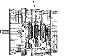
Shift the Rail C Sliding Clutch to the neutral position (if necessary).
Shift the Rail C Sliding Clutch into the Primary Drive Gear engagement position (fore).
Inspect the Rail C Sliding Clutch clutching teeth for wear.
Return the Rail C Sliding Clutch to neutral.
Shift the Rail C Sliding Clutch into the Secondary Driven Gear engagement position (aft).
Inspect the Rail C Sliding Clutch clutching teeth for wear.
Return the Rail C Sliding Clutch to neutral.
- If the Rail C Sliding Clutch shifts into all three positions and no clutching teeth wear is present, contact Eaton Cummins Automated Transmission Technologies for further diagnostic instructions. For Help Line phone numbers, go to Contact Information
- If the Rail C Sliding Clutch does not shift into all three positions or clutching teeth wear is present, reference Primary Drive Gear Replacement procedure for replacing the Primary Drive Gear and Rail C Sliding Clutch, and Secondary Driven Gear. Go to Step V.
Procedure B
STEP A
Purpose: Verify mechanical condition of the Primary and Secondary Drive Gears.
Inspect the Secondary Drive Gear for excessive for and aft movement.
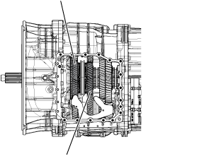
Inspect the Primary Drive Gear for excessive fore and aft movement.
- If excessive gear movement is evident, inspect for cause of excessive gear movement and repair. Go to Step V.
- If no excessive gear movement is evident, go to Procedure B, Step B.
Procedure B
STEP B
Purpose: Verify mechanical condition of the Rail B Synchronizer and clutching teeth.
Inspect the Rail B Synchronizer Sliding Sleeve yoke slot for wear.
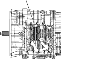
Install the Rail B Synchronizer Engagement Tool (RR1088TR).
Note: Reference Appendix, Manually Actuate Rail B Procedure.
Shift Rail B Synchronizer Sliding Sleeve into neutral (if necessary).
Shift the Rail B Synchronizer Sliding Sleeve into the Secondary Drive Gear engagement position (fore).
Inspect the Primary Drive Gear and synchronizer ring clutching teeth for wear.
Return the Rail B Synchronizer Sliding Sleeve to neutral.
Shift the Rail B Synchronizer Sliding Sleeve into the Primary Drive Gear engagement position (aft).
Inspect the Secondary Drive Gear and synchronizer ring clutching teeth for wear.
Return the Rail B Synchronizer Sliding Sleeve to neutral.
- If the Rail B Synchronizer Sliding Sleeve shifts into all three positions and no clutching teeth wear is present, contact Eaton Cummins Automated Transmission Technologies for further diagnostic instructions. For Help Line phone numbers, go to Contact Information.
- If the Rail B Synchronizer Sliding Sleeve does not shift into all three positions or clutching teeth wear is present, reference the Primary Drive Gear Replacement procedure for replacement of the Primary Drive Gear. Replace the Rail B Synchronizer Assembly and the Secondary Drive Gear. Go to Step V.
Procedure C
STEP A
Purpose: Verify mechanical condition of the Primary Drive Gear and Secondary Driven Gear.
Inspect the Primary Drive Gear for excessive fore and aft movement.
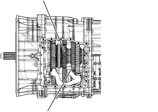
Inspect the Secondary Driven Gear for excessive for and aft movement.
- If excessive gear movement is evident, inspect for cause of excessive gear movement and repair. Go to Step V.
- If no excessive gear movement is evident, go to Procedure C, Step B.
Procedure C
STEP B
Purpose: Verify mechanical condition of the Rail C Sliding Clutch and clutching teeth.
Inspect the Rail C Sliding Clutch yoke slot for wear.

Shift the Rail C Sliding Clutch to the neutral position (if necessary).
Shift the Rail C Sliding Clutch into the Primary Drive Gear engagement position (fore).
Inspect the Rail C Sliding Clutch clutching teeth for wear.
Return the Rail C Sliding Clutch to neutral.
Shift the Rail C Sliding Clutch into the Secondary Driven Gear engagement position (aft).
Inspect the Rail C Sliding Clutch clutching teeth for wear.
Return the Rail C Sliding Clutch to neutral.
- If the Rail C Sliding Clutch shifts into all three positions and no clutching teeth wear is present, contact Eaton Cummins Automated Transmission Technologies for further diagnostic instructions. For Help Line phone numbers, go to Contact Information.
- If the Rail C Sliding Clutch does not shift into all three positions or clutching teeth wear is present, refer to the Primary Drive Gear Replacement procedure for replacing the Primary Drive Gear and Rail C Sliding Clutch, and Secondary Driven Gear. Go to Step V.
Procedure D
STEP A
Purpose: Verify mechanical condition of the Primary Driven Gear and Reverse Gear
Inspect the Primary Driven Gear for excessive fore and aft movement.
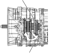
Inspect the Reverse Gear for excessive fore and aft movement.
- If excessive gear movement is evident, inspect for cause of excessive gear movement and repair. Go to Step V.
- If no excessive gear movement is evident, go to Procedure D, Step B.
Procedure D
STEP B
Purpose: Verify mechanical condition of the Rail D Sliding Clutch and clutching teeth.
Inspect the Rail D Sliding Clutch yoke slot for wear.
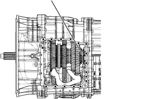
Shift the Rail D Sliding Clutch to the neutral position (if necessary).
Shift the Rail D Sliding Clutch into the Primary Driven Gear engagement position (fore).
Inspect the Rail D Sliding Clutch clutching teeth for wear.
Return the Rail D Sliding Clutch to neutral.
Shift the Rail D Sliding Clutch into the Reverse Gear engagement position (aft).
Inspect the Rail D Sliding Clutch clutching teeth for wear.
Return the Rail D Sliding Clutch to neutral.
- If the Rail D Sliding Clutch shifts into all three positions and no clutching teeth wear is present, contact Eaton Cummins Automated Transmission Technologies for further diagnostic instructions. For Help Line phone numbers, go to Contact Information.
- If the Rail D Sliding Clutch does not shift into all three positions or clutching teeth wear is present, replace the Rail D Sliding Clutch, Primary Driven Gear and Reverse Gear. Go to Step V.
STEP V
Key off.
Reconnect all connectors and verify that all components are properly installed.
Key on with engine off.
Connect ServiceRanger.
Go to “Fault Codes”.
Select “Clear All Faults”.
Operate vehicle and attempt to reset the fault code or duplicate the previous complaint.
Check for fault codes using ServiceRanger.
- If no fault codes sets and the vehicle operates properly, test complete.
- If Fault Code 617, 740, 760, 775 sets Active during operation, contact Eaton Cummins Automated Transmission Technologies for further diagnostic instructions. For Help Line phone numbers, go to “Contact Information” on page 4.
- If a fault code other than 617, 740, 760, 775 sets Active, go to Endurant HD Troubleshooting Guide and troubleshoot per the Fault Code Isolation Procedure Index.
Warranty Information
Reference the relevant warranty information provided in service bulletin TAIB-0994.