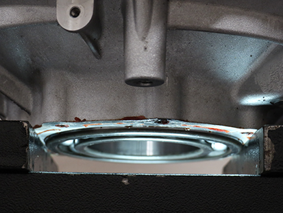
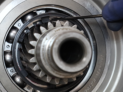
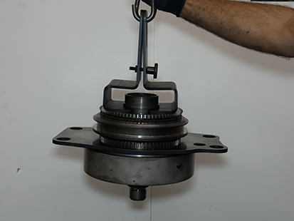
Rear Housing

Special Instructions

Warning
Rear Housing weighs approximately 170 lbs. Keep fingers clear of pinch point between Rear Housing and other surfaces. Dropping Rear Housing could result in major vehicle component damage, severe injury or death.

Special Tools

  • Reaction Plate Alignment Pins (RR1091TR)
  • Range Assembly Removal & Installation Tool (RR1065TR)
  • Rear Housing Stand (RR1069TR)
  • Input Shaft Bearing Removal and Installation Tool (RR1075TR)
  • Output Bearing Removal and Installation Tool (RR1089TR)
  • Universal Driver Handle (OE8044-T0)

Component Identification
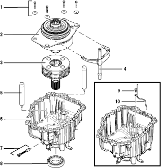
_Graphics/_LineArt/TRTS0950_RearHousingAssemblyDA_ID.png

1. Cap Screws and Washers (x4) - 13 mm

2. Range Synchronizer Assembly

3. Planetary Output Shaft Assembly

4. Shift Rail E

5. Reaction Plate Alignment Pins (x2)

6. Rear Housing

7. Rail E Detent

8. Output Bearing

9. Cap Screw (x1) - 8 mm

10. Rear PTO Lube Tube (Dual PTO model only)

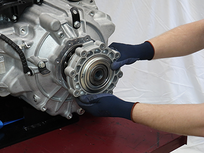
Remove the Rear Bearing Cover

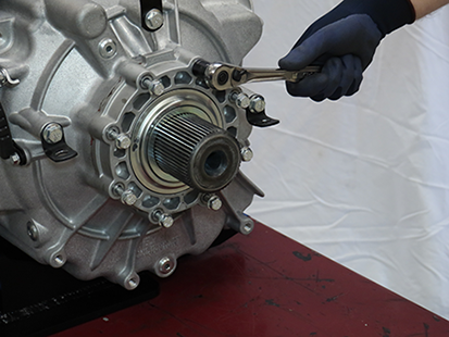
  1. Remove the 8 Rear Bearing Cover 13 mm Cap Screws.
    _Graphics/_Raster/IMG_0307.png
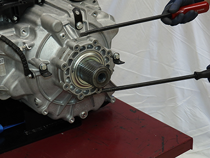
  2. Using a pry bar, separate the Rear Bearing Cover from the rear housing.

    Note: Two pry points located at 12 and 6 o’clock.
    _Graphics/_Raster/IMG_0308.png
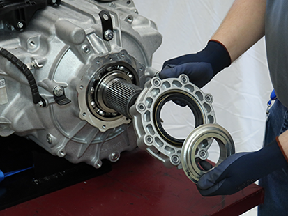
  3. Remove the Rear Bearing Cover, Wear Sleeve and Dust Cover.

    Notice
    If replacing the Output Seal, a new Rear Bearing Cover is required when reinstalling or an oil leak may occur.
    Notice
    Ensure Output Shaft Seal is pressed in new Rear Bearing Cover.
    _Graphics/_Raster/IMG_0309.png_Graphics/_Raster/IMG_0310.png
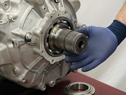
  4. Remove the O-ring.

    _Graphics/_Raster/IMG_7085.png
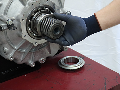
  5. Remove the Output Shaft Thrust Washer.
    _Graphics/_Raster/IMG_0320.png

Disassemble the Rear Housing

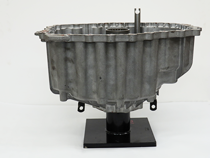
  1. Place Rear Housing on Rear Housing Stand (RR1069TR).

    Warning
    Rear Housing weighs approximately 170 lbs. Keep fingers clear of pinch point between Rear Housing and other surfaces. Dropping Rear Housing may result in major vehicle component damage, severe injury or death.
    _Graphics/_Raster/TRSM0950_0250.png
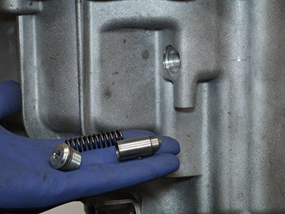
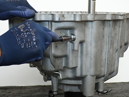
  2. Remove Rail E Detent Plug with a 6 mm hex key.

    Note: Detent Plug is under spring pressure.
    _Graphics/_Raster/TRSM0950_0244.png
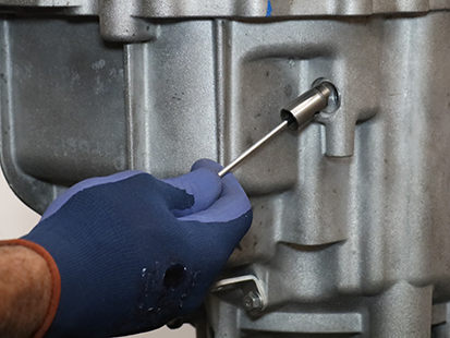
  3. Remove the Rail E Spring and Detent using a magnet.
    _Graphics/_Raster/TRSM0950_0196.png_Graphics/_Raster/TRSM0950_0198.png
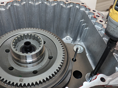
  4. Remove 4 Reaction Plate 13 mm cap screws and washers.
    _Graphics/_Raster/IMG_3036.png
  5. Install 2 Reaction Plate Alignment Pins (RR1091TR) onto Reaction Plate dowels.

    Notice
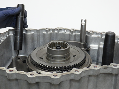
    Failure to use Reaction Plate Alignment Pins (RR1091TR) results in component damage.
    _Graphics/_Raster/TRSM0950_0251.png
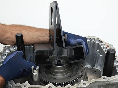
  6. Install Range Assembly Removal & Installation Tool (RR1065TR) into Sun Gear groove.

    Caution
    Failure to properly secure tool could result in damage to component(s) or personal injury.
    Notice
    Fully seat tool into groove and hand tighten until tool is secure.
    _Graphics/_Raster/TRSM0950_0220.png_Graphics/_Raster/TRSM0950_0253.png
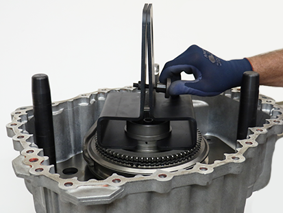
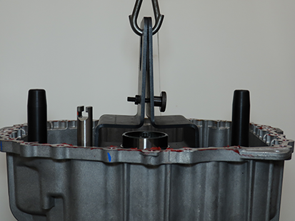
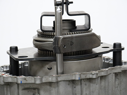
  7. Lift and remove Range Synchronizer Assembly from Rear Housing.

    Caution
    Range Synchronizer Assembly weighs approximately 70 lbs. Failure to properly secure and lift the assembly may result in component damage, serious injury or death.
    Notice
    Use an appropriate lifting device to safely lift component.

    Note: Rotate Sun Gear to ease removal.
    _Graphics/_Raster/IMG_3054.png_Graphics/_Raster/TRSM0950_0224.png
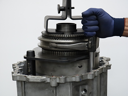
  8. Hold Shift Rail E to the Range Synchronizer while removing Range Synchronizer Assembly from Rear Housing.
    _Graphics/_Raster/TRSM0950_0225.png
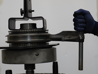
  9. After Range Synchronizer Assembly clears the housing, remove Shift Rail E.
    _Graphics/_Raster/TRSM0950_0228.png
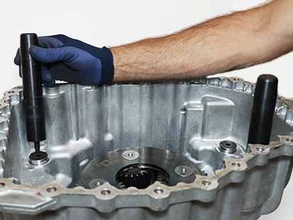
  10. Remove Reaction Plate Alignment Pins (RR1091TR).
    _Graphics/_Raster/TRSM0950_0242.png
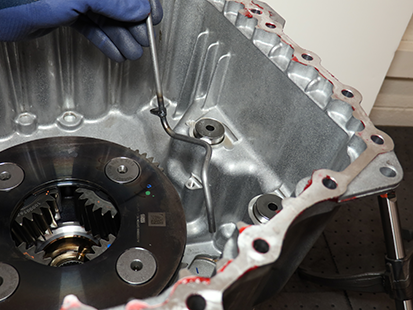
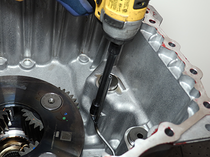
  11. For Dual PTO transmissions, remove the Rear PTO Lube Tube 8 mm cap screw and remove tube.
    _Graphics/_Raster/IMG_3065.png_Graphics/_Raster/IMG_3071.png
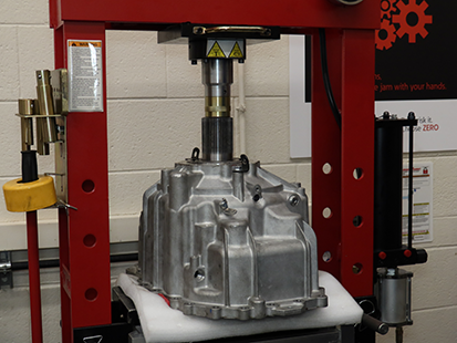
  12. Place Rear Housing in press with Output Shaft up.

    Caution
    Rear Housing with the Planetary Output Shaft Assembly weighs approximately 60 lbs. Keep fingers clear of pinch point between Rear Housing and other surfaces. Dropping Rear Housing could result in component damage and/or personal injury.
    Notice
    Place soft material under Planetary Output Shaft Assembly to cushion removal from Rear Housing.
    Notice
    Support the Rear Housing to avoid damaging the housing and sealing surface.
  13. Press Planetary Output Shaft Assembly out of Rear Housing.
    _Graphics/_Raster/TRSM0950_105_OutputShaftAmblyRem1.png
  14. Remove Rear Housing and Planetary Output Shaft Assembly from press.

    Caution
    Rear Housing with the Planetary Output Shaft Assembly weighs approximately 60 lbs. Keep fingers clear of pinch point between Rear Housing and other surfaces. Dropping Rear Housing and Planetary Output Shaft Assembly could result in component damage and/or personal injury.
  15. Install Rear Housing in press and support housing on Rear Bearing Cover sealing surface.

    Caution
    Rear Housing weighs approximately 15 lbs. Keep fingers clear of pinch point between Rear Housing and other surfaces. Dropping the Rear Housing may result in major vehicle component damage, severe injury or death.
    Notice
    Support the Rear Housing to avoid damaging the housing and sealing surface.
    _Graphics/_Raster/IMG_8351.png
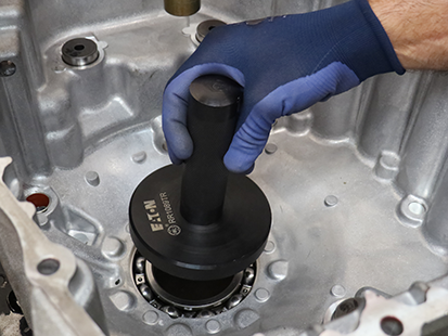
  16. Place Output Bearing Removal and Installation Tool (RR1089TR) and Universal Driver Handle (OE8044-T0) onto Output Bearing.
    _Graphics/_Raster/TRSM0950_0207.png
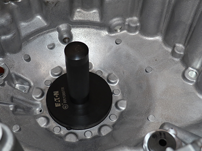
  17. Press Output Bearing from Rear Housing.
    _Graphics/_Raster/TRSM0950_0208.png

Assemble the Rear Housing

  1. Place Rear Housing into press.

  2. Place Output Bearing onto Rear Housing.
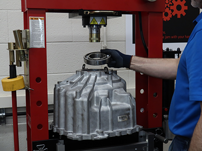
    _Graphics/_Raster/TRSM0950_113_InstallOutputBear.png
  3. Place Output Bearing Removal and Installation tool (RR1089TR) onto Output Bearing.

    Notice
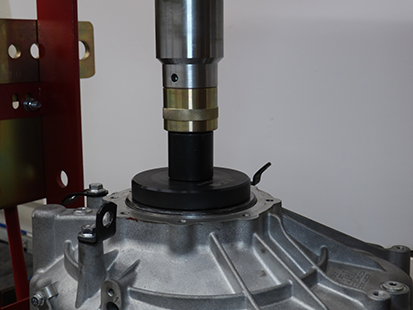
    Do not over press bearing into Rear Housing. Over pressing could result in component damage.
    _Graphics/_Raster/TRSM0950_0235.png
  4. Press Output Bearing into Rear Housing.

  5. Verify Output Bearing is fully seated.
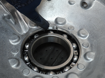
    _Graphics/_Raster/TRSM0950_118_FullySeatedOutputBearing.png
  6. Place Rear Housing Stand (RR1069TR) on Press.
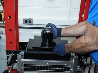
    _Graphics/_Raster/IMG_3557.png
  7. Place Rear Housing on Rear Housing Stand (RR1069TR).

    Caution
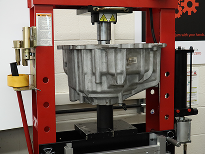
    Rear Housing weighs approximately 15 lbs. Keep fingers clear of pinch point between Rear Housing and other surfaces. Dropping Rear Housing could result in component damage and/or personal injury.
    _Graphics/_Raster/TRSM0950_121.png
  8. Place Planetary Output Shaft Assembly into Output Bearing.

    Caution
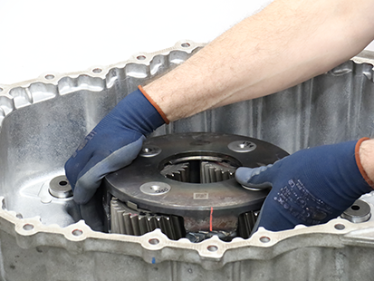
    Planetary Output Shaft Assembly weighs approximately 45 lbs. Keep fingers clear of pinch point between Planetary Output Shaft Assembly and other surfaces. Dropping Planetary Output Shaft Assembly could result in component damage and/or personal injury.
    _Graphics/_Raster/TRSM0950_120.png
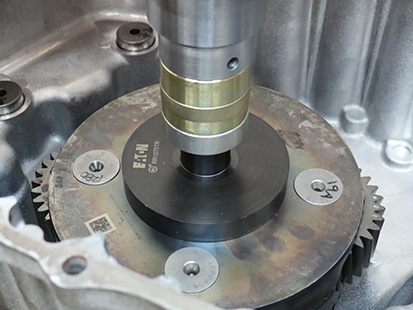
  9. Place Input Shaft Bearing Removal and Installation Tool (RR1075TR) onto Planetary Output Shaft Assembly.

  10. Press Planetary Output Shaft Assembly through output bearing until fully seated.
    _Graphics/_Raster/TRSM0950_122_InstallOutputSCAmbly.png
  11. Remove Rear Housing from press.

    Caution
    Rear Housing with the Planetary Output Shaft Assembly weighs approximately 60 lbs. Keep fingers clear of pinch point between Rear Housing and other surfaces. Dropping Rear Housing and Planetary Output Shaft Assembly could result in component damage and/or personal injury.
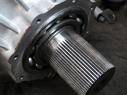
  12. Verify Planetary Output Shaft Assembly is fully seated in Output Bearing.
    _Graphics/_Raster/TRSM0950_123_FullySeatedCarrierShaftAmbly.png
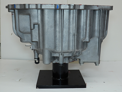
  13. Place rear housing on Rear Housing Stand (RR1069TR).
    _Graphics/_Raster/IMG_3322.png
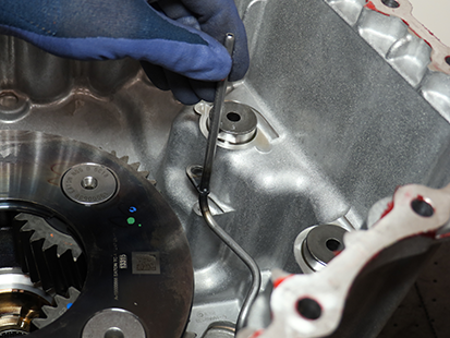
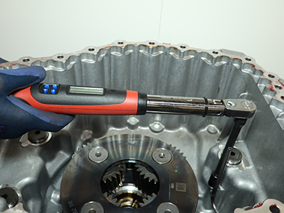
  14. For Dual PTO Transmissions, install Rear PTO Lube Tube and 8 mm cap screw into Rear Housing and torque to 8.8 - 10.4 Nm (6-8 lb-ft).
    _Graphics/_Raster/IMG_3070.png_Graphics/_Raster/IMG_3073.png
  15. Install Reaction Plate Alignment Pins (RR1091TR) in Rear Housing.

    Notice
    Failure to use Reaction Plate Alignment Pins (RR1091TR) results in component damage.
    _Graphics/_Raster/TRSM0950_0242.png
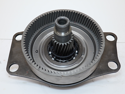
  16. Inspect plastic Oil Slinger to ensure it is locked into place by three locking tab pins.
    _Graphics/_Raster/IMG_4688.png_Graphics/_Raster/TRSM0950_0238.png
  17. Install Range Assembly Removal & Installation Tool (RR1065TR) into Sun Gear groove.

    Caution
    Failure to properly secure tool could result in component damage or personal injury.
    Notice
    Fully seat tool into groove and hand tighten until tool is secure.
  18. Lift Range Synchronizer Assembly with Range Assembly Removal & Installation tool (RR1065TR).

    Caution
    Range Synchronizer Assembly weighs approximately 70 lbs. Failure to properly secure and lift the assembly may result in component damage, serious injury or death.
    Notice
    Use an appropriate lifting device to safely lift component.
    _Graphics/_Raster/IMG_3554.png
  19. Install and hold Shift Rail E to Range Synchronizer Assembly.

    Note: Ensure the notched end of Shift Rail E is facing up.

    _Graphics/_Raster/TRSM0950_0228.png
  20. Lower the Range Synchronizer Assembly and Shift Rail E into Rear Housing.

    Note: Align Range Synchronizer Assembly to the Reaction Plate Alignment Pins (RR1091TR) and Shift Rail E into Rear Housing.

    Note: Rotate Sun Gear to ease installation.

    _Graphics/_Raster/TRSM0950_0225.png
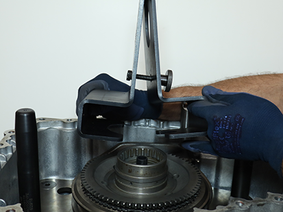
  21. Remove Range Assembly Removal and Installation tool (RR1065TR).
    _Graphics/_Raster/IMG_3547.png
  22. Remove Reaction Plate Alignment Pins (RR1091TR).

    _Graphics/_Raster/TRSM0950_0251.png
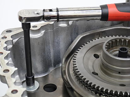
  23. Install 4 Reaction Plate cap screws and washers and torque to 21 - 25 Nm (16 - 19 lb-ft).
    _Graphics/_Raster/TRSM0950_0160.png
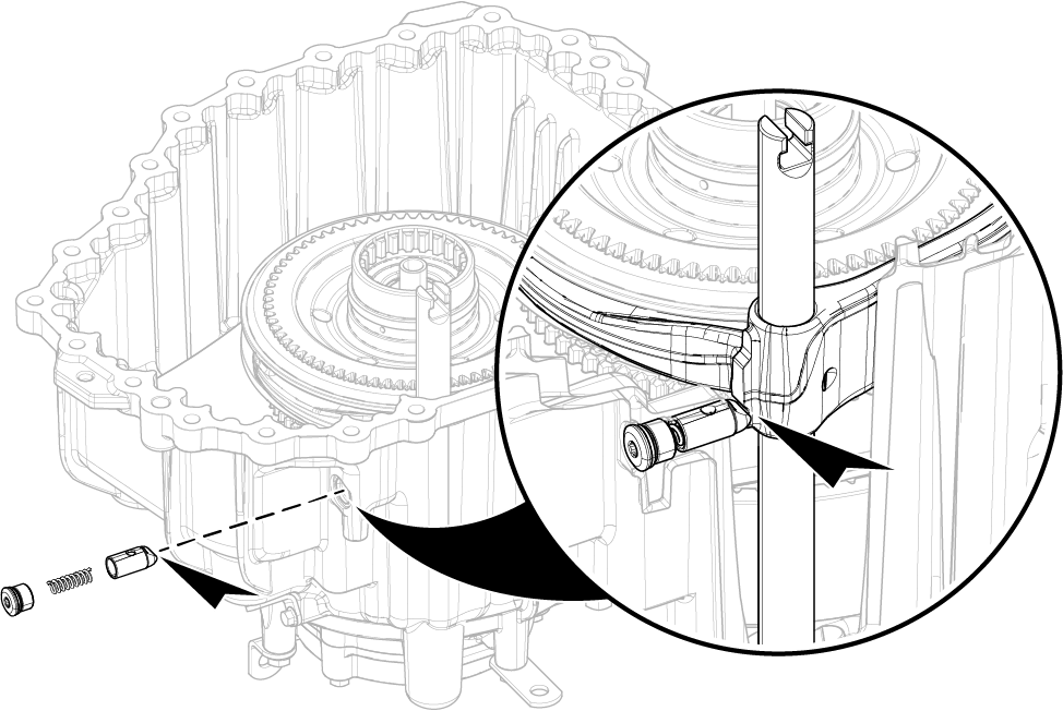
  24. Install Rail E Detent, Spring and Plug.
    _Graphics/_LineArt/TRSM0950_RailEDetentPlug_xplnr.png
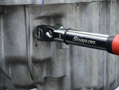
  25. Torque detent plug to 24.5 - 29.5 Nm (16-19 lb-ft).

    Notice
    Do not over-torque detent plug or transmission damage may occur.
    _Graphics/_Raster/TRSM0950_0165.png