Lower Countershaft Cover and Inertia Brake
Special Instructions
None
Special Tools
- Inertia Disc Assembly Tool (RR1093TR)
Component Identification
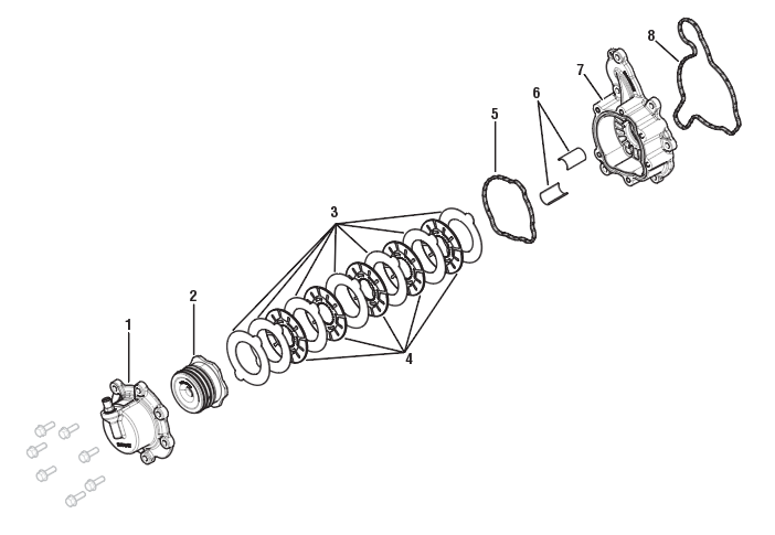 |
1. Inertia Brake Cover 2. Inertia Brake Piston 3. Steel Discs (x7) 4. Friction Discs (x5) 5. O-ring - Front 6. Wear Guides (x2) 7. Inertia Brake Housing 8. O-ring - Rear |
Disassemble the Inertia Brake
Remove the clutch pack from the Inertia Brake Housing.
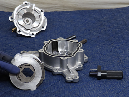
Remove the 2 wear guides from the Inertia Brake Housing.
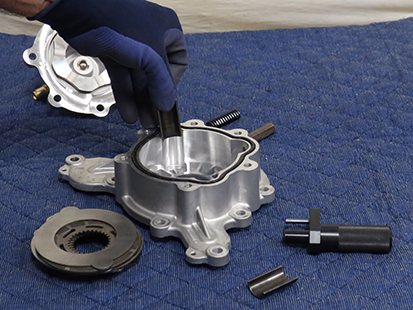
Remove O-ring from the front of the Inertia Brake Housing.
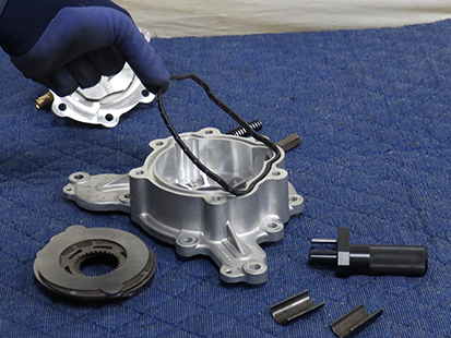
Remove O-ring from the rear of the Inertia Brake Housing.
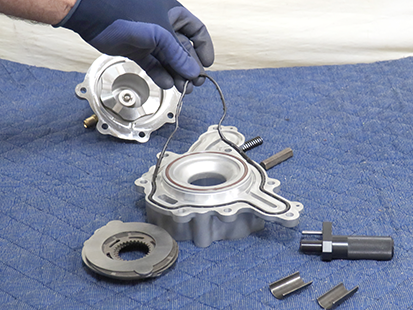
Remove O-ring from rear of Inertia Brake Housing that pin's the Countershaft Bearing.
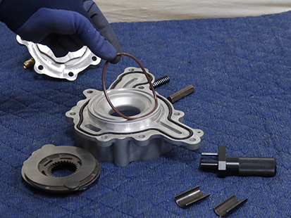
Assemble the Inertia Brake
Insert the O-ring into the groove on the rear of the Inertia Brake Housing until fully seated.
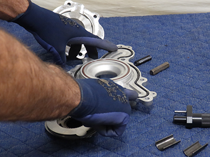
Insert the O-ring into the inner grove on the rear of the inertia Brake Housing that Pin's the counter shaft Bearing.
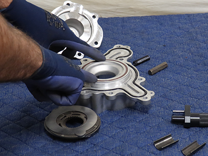
Insert the O-ring into the groove on the front of the Inertia Brake Housing until fully seated.
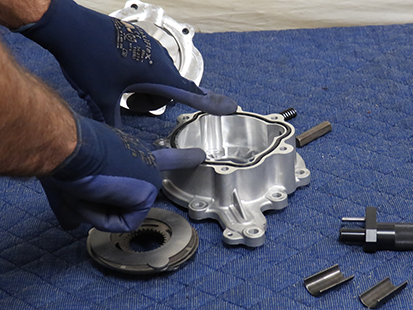
Install the 2 Wear Guides in the Inertia Brake Housing.
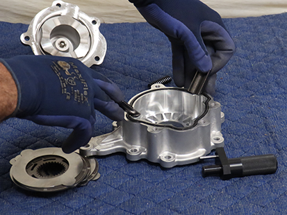
Install the inertia brake clutch pack in the order shown below:
- 1 Steel Disc
- 1 Friction Disc
- 1 Steel Disc
- 1 Friction Disc
- 1 Steel Disc
- 1 Friction Disc
- 1 Steel Disc
- 1 Friction Disc
- 1 Steel Disc
- 1 Friction Disc
- 1 Steel Disc
- 1 Steel Disc
Note: Steel Discs align with Wear Guides. Friction Discs spline to the lower countershaft.
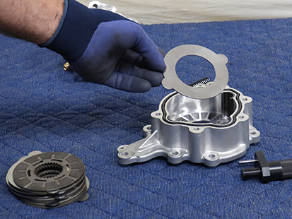
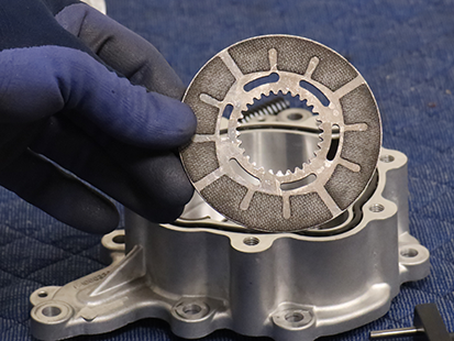
Place all Friction Discs so alignment holes line up when stacking Steel Disc and Friction Disc.
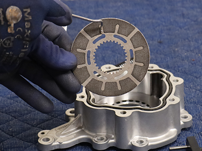
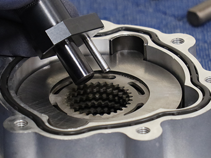
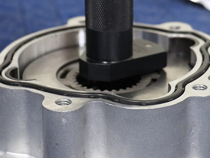
Insert the smallest diameter pin on Inertia Disc Assembly tool (RR1093TR) through all of the Friction disc alignment holes in the Inertia Brake Housing.
Note: See Lower Countershaft Cover and Inertia Brake Service Procedure for installation of assembly onto Lower Countershaft splines.
