Lower Countershaft Cover and Inertia Brake
Special Instructions
None
Special Tools
- Inertia Disc Assembly Tool (RR1093TR)
Component Identification
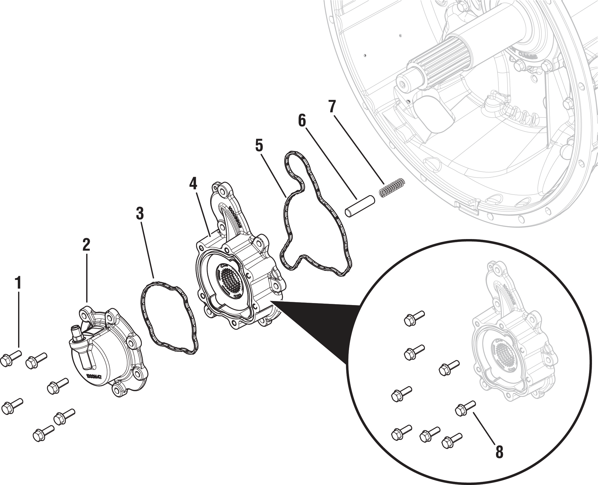 |
1. Inertia Brake Cover Cap Screws (x6) - 13 mm 2. Inertia Brake Cover 3. Inertia Brake Cover O-ring 4. Inertia Brake Housing 5. Inertia Brake Housing O-ring 6. Piston Pin 7. Return Spring 8. Inertia Brake Housing Cap Screws (x8) - 13 mm |
Drain Oil
Locate the Oil Drain Plug on the back of the rear housing.
Place a suitable container under the Oil Drain Plug.
Note: If reusing oil, use a clean container free of contamination and debris.
Remove the Oil Drain Plug with a 8 mm hex key and drain the oil.
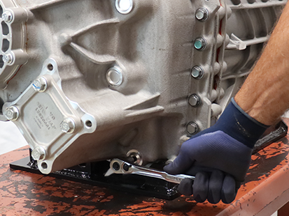
If PTO-equipped, remove PTO and drain the oil.
Inspect Oil Drain Plug and O-ring for damage. If damaged, replace the Oil Drain Plug; O-ring is serviced with plug.
Install the Oil Drain Plug (8 mm) and torque to 24.5-29.5 Nm (18-22 lb-ft).
Notice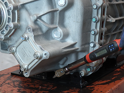
Manually Vent Linear Clutch Actuator (LCA)
Key off.
Set vehicle parking brake and chock wheels.
WarningLoosen the 4 Linear Clutch Actuator (LCA) cap screws 1-2 turns each with a T45 Torx.
Note: Residual air pressure in the LCA cylinder exhausts between the LCA and Mechatronic Transmission Module (MTM) housing when the cap screws are loosened.
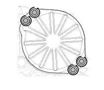
Tighten the 4 LCA to MTM T45 cap screws and torque to 23-27 Nm (17-21 lb-ft).
Remove the Transmission
Disconnect negative battery cable.
Refer to OEM guidelines for transmission removal.
Remove the Release Bearing and Clutch Release Yoke
Remove the Release Bearing by sliding the bearing off the input shaft.
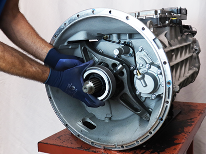
Pull to free the lower Clutch Release Yoke socket from the lower pivot on the clutch housing.
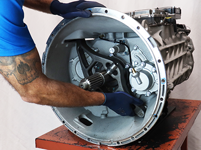
Pull to free the upper Clutch Release Yoke socket from the Linear Clutch Actuator (LCA) rod end.
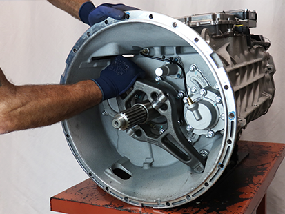
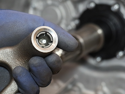
Inspect the plastic socket inserts in the Clutch Release Yoke to verify none of the fingers are missing or damaged.
Note: If the plastic insert is damaged, replace the Clutch Release Yoke assembly.
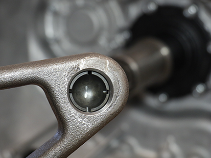
Remove the Lower Countershaft Cover
Depress and hold collar on air line fitting and disconnect the air line from the Inertia Brake Cover.
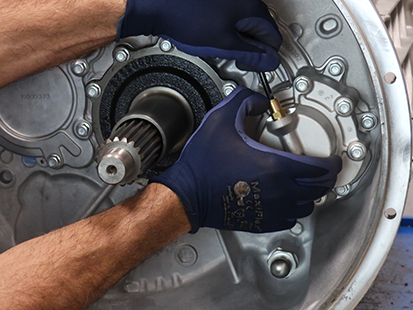
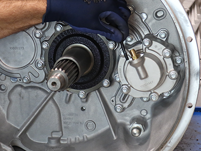
Remove the 6 Inertia Brake Cover 13 mm cap screws.
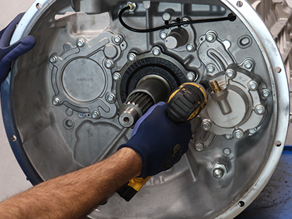
Remove the Inertia Brake Cover and Housing as an assembly.
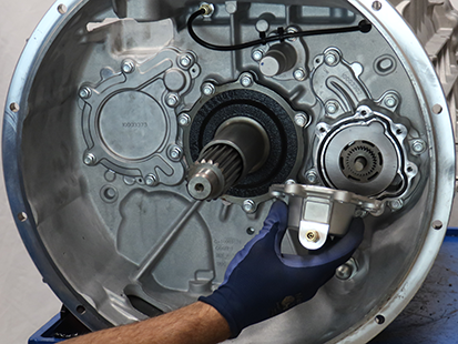
Remove Piston Pin from the end of the Lower Countershaft.
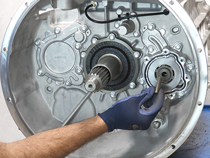
Remove the Return Spring from the end of the Lower Countershaft using a magnet.
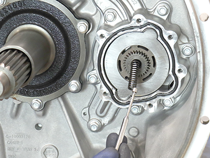
Remove the Inertia Brake Housing
Remove the 8 Inertia Brake Housing 13 mm cap screws.
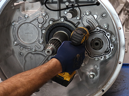
Remove the Inertia Brake Housing as an assembly.
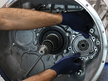
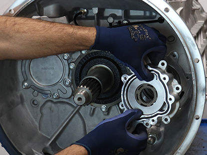
Install the Inertia Brake Housing
Insert the smallest diameter pin of the Inertia Disc Assembly tool (RR1093TR) into the formed opening of all the (5) Inertia Brake Friction disc.
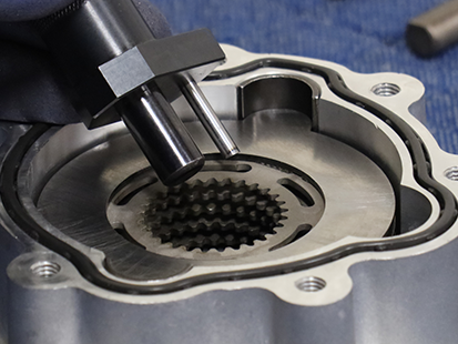
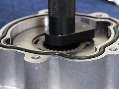
Install Inertia Brake Housing with Inertia Disc Assembly tool (RR1093TR) inserted.
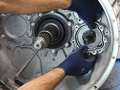
Remove the Inertia Disc Assembly tool (RR1093TR)
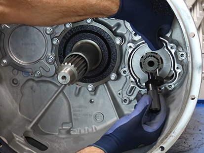
Ensure all Inertia Brake Friction Discs have fully engaged the Lower Countershaft splines.
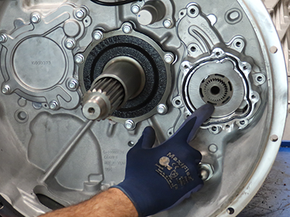
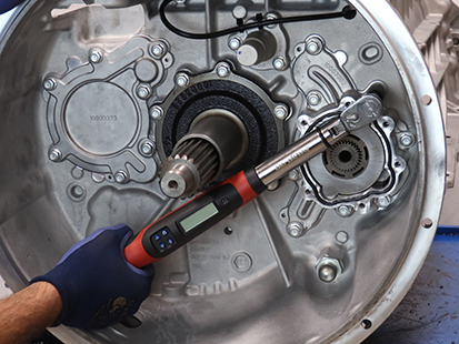
Install the 8 Inertia Brake Housing 13 mm cap screws and torque to 21 - 25 Nm (16-19 lb.Dft).
Install the Lower Countershaft Cover
Clean sealing surfaces on the Clutch Housing and Inertia Brake Housing.
Install the Return Spring into the Lower Countershaft.
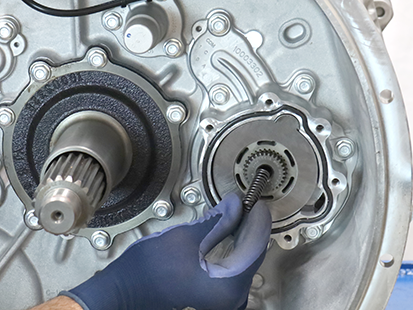
Install the Piston Pin into the Lower Countershaft.

Install the Inertia Brake Cover onto the housing.

Install the 6 Inertia Brake Cover 13 mm cap screws and torque to 21-25 Nm (16-19 lb-ft) in a criss-cross pattern.
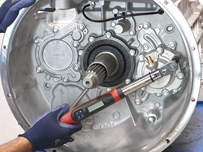
Insert air line in push-to-connect fitting on the Inertia Brake Cover.

Remove the Linear Clutch Actuator (LCA)
Loosen the 4 LCA cap screws 1-2 turns each with a T45 Torx.
NoticeNote: Residual air pressure in the LCA cylinder exhausts between the LCA and MTM housing when the cap screws are loosened.
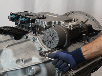
Remove the 4 LCA cap screws
Remove the LCA from the MTM.
NoticeNote: LCA piston rod end is seated in the release yoke socket; pull to release rod end from socket.
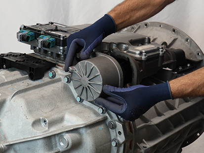
Inspect the plastic socket insert in the release yoke through the LCA opening using a flashlight to verify none of the fingers are missing or damaged.
Note: If the plastic insert is damaged, replace the release yoke assembly.
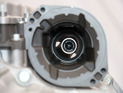
Reset and Install Linear Clutch Actuator (LCA)
Note: Linear Clutch Actuator (LCA) can be installed with transmission in-vehicle.
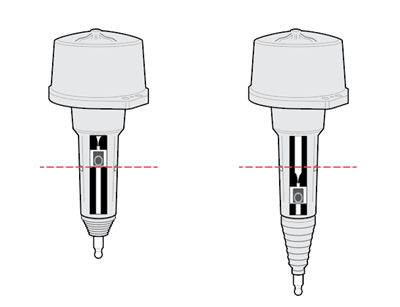
Inspect LCA to determine next steps, reference images below:
- If LCA is locked in the reset position, go to Step 5 and install Linear Clutch Actuator.
- If LCA is not locked in the reset position, go to Step 2.
Locked in Reset Position
Not Locked In Reset Position
Place LCA push rod on a clean, flat surface. Tightly grasp LCA housing with both hands and push down on push rod to lock LCA into the reset position.
Caution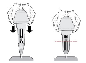
Inspect LCA to determine next steps, reference images below:
- If LCA remains locked in the reset position, go to Step 4.
- If LCA does not remain locked in the reset position, go to Step 2, repeat reset procedure.
Note: If LCA cannot be locked into the reset position, replace LCA.
CautionLocked in Reset Position
Not Locked In Reset Position

Clean all sealing surfaces on the MTM and LCA with a lint free cloth.
NoticeInsert the LCA into the MTM.
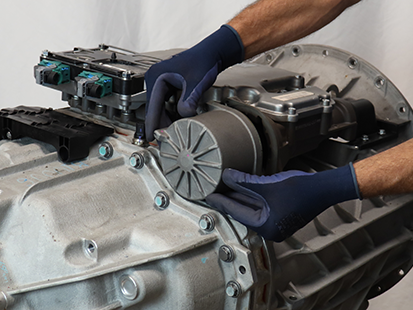
Install 4 LCA T45 cap screws and torque to 23-28 Nm (17-21 lb-ft) in a criss-cross pattern.
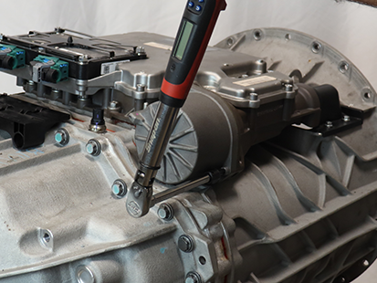
Install the Release Bearing and Clutch Release Yoke
Install the upper Release Yoke socket over the rod end of the Linear Clutch Actuator (LCA) and press until attached.
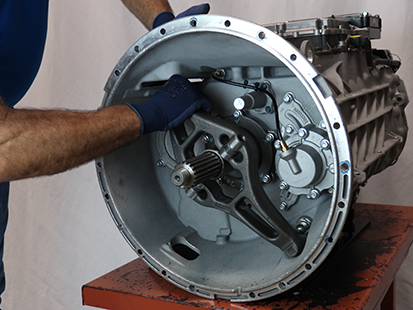
Install the lower Release Yoke socket over the lower pivot on the clutch housing and press until attached.
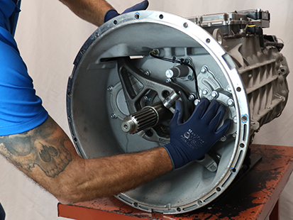
Slide the Release Bearing over the input shaft and into the Release Yoke.
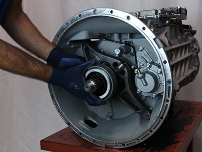
Install the Transmission
Refer to OEM guidelines for transmission installation.
Connect negative battery cable.
Fill Oil
Note: Perform the transmission fill procedure with transmission installed in vehicle to ensure proper transmission angle.
Remove the Oil Fill Plug with a 6 mm hex key.
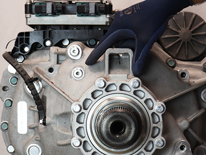
Place a suitable container under the Oil Check Plug and remove the Oil Check Plug with a 6 mm hex key.
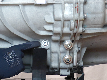
Fill the transmission with PS-386 lube until a small amount of oil runs out of the Oil Check Plug hole.
Note: Fill capacity is approximately 12.0 liters (25.4 pints) depending on the transmission angle.
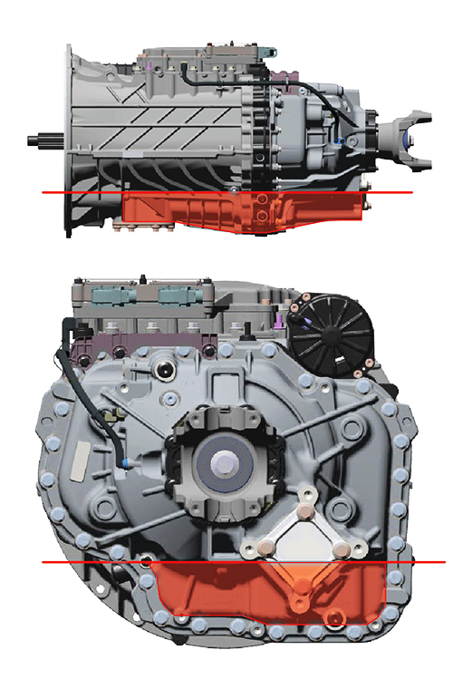
Inspect Oil Check Plug and O-ring for damage. If damaged, replace the Oil Check Plug; O-ring is serviced with plug.
Install the Oil Check Plug (6 mm) and torque to 24.5-29.5 Nm (18-22 lb-ft).
Notice
Inspect Oil Fill Plug and O-ring for damage. If damaged, replace the Oil Fill Plug; O-ring is serviced with plug.
Install the Oil Fill Plug (6 mm) and torque to 24.5-29.5 Nm (18-22 lb-ft).
Notice
Clutch and Rail Calibration
To ensure proper operation, the TCM, clutch, MTM and transmission require a Clutch and Rail Calibration. Calibrations are automatically initiated when:
- LCA is in the reset position
- Transmission is “N” (Neutral)
- Key on engine running
- Vehicle air system pressure at operating range
Note: Vehicle display may indicate a flashing “CC” and “F” in gear display.
Set vehicle parking brake and chock wheels.
Ensure the driveline is connected between the transmission and axle.
Note: Clutch and Rail Calibrations cannot complete if the transmission output shaft is allowed to rotate.
Key on with engine running.
Allow vehicle air pressure to build to governor cut-off.
Note: Clutch and Rail Calibrations automatically initiate when vehicle air pressure reaches approximately 100 psi.
Ensure “N” (Neutral) is selected and engine is running. Wait approximately 2 minutes for calibrations to complete.
Notice- If vehicle display indicates a solid “N” (Neutral) in gear display, calibrations are complete. Key off, go to Step 6.
- If vehicle display continues to indicate a flashing “CC” and/or “F” in gear display or service transmission message, go to Step 5.
Key off and wait 1 minute.
Key on with engine off.
Connect ServiceRanger.
Go to “Fault Codes”.
- If an Active transmission fault code is set, go to Endurant XD Troubleshooting Guide TRTS0960 Diagnostic Procedure.
- If no Active transmission fault codes are set, select “Clear Eaton Faults” and follow on-screen prompts. Go to Step 9.
Disconnect ServiceRanger.
Key off.
Inspect transmission for a PTO.
- If not PTO-equipped, process complete.
- If PTO-equipped, start the engine and run for 1 to 2 minutes to fill the PTO with oil, key off and repeat the Fill Oil Procedure.
Caution