Main Shaft
Special Instructions
Note: The Main Shaft End-Play Service Procedure is required if one or more of the following parts are replaced:
- Any Counter Shaft
- Main Housing
- Any Main Shaft or Main Shaft Component
- Input Shaft Bearing
- Intermediate Housing
Special Tools
- Main Shaft Repair Kit (RR2016TR)
- * Basic Service Repair Kit (RR2014TR)
Component Identification
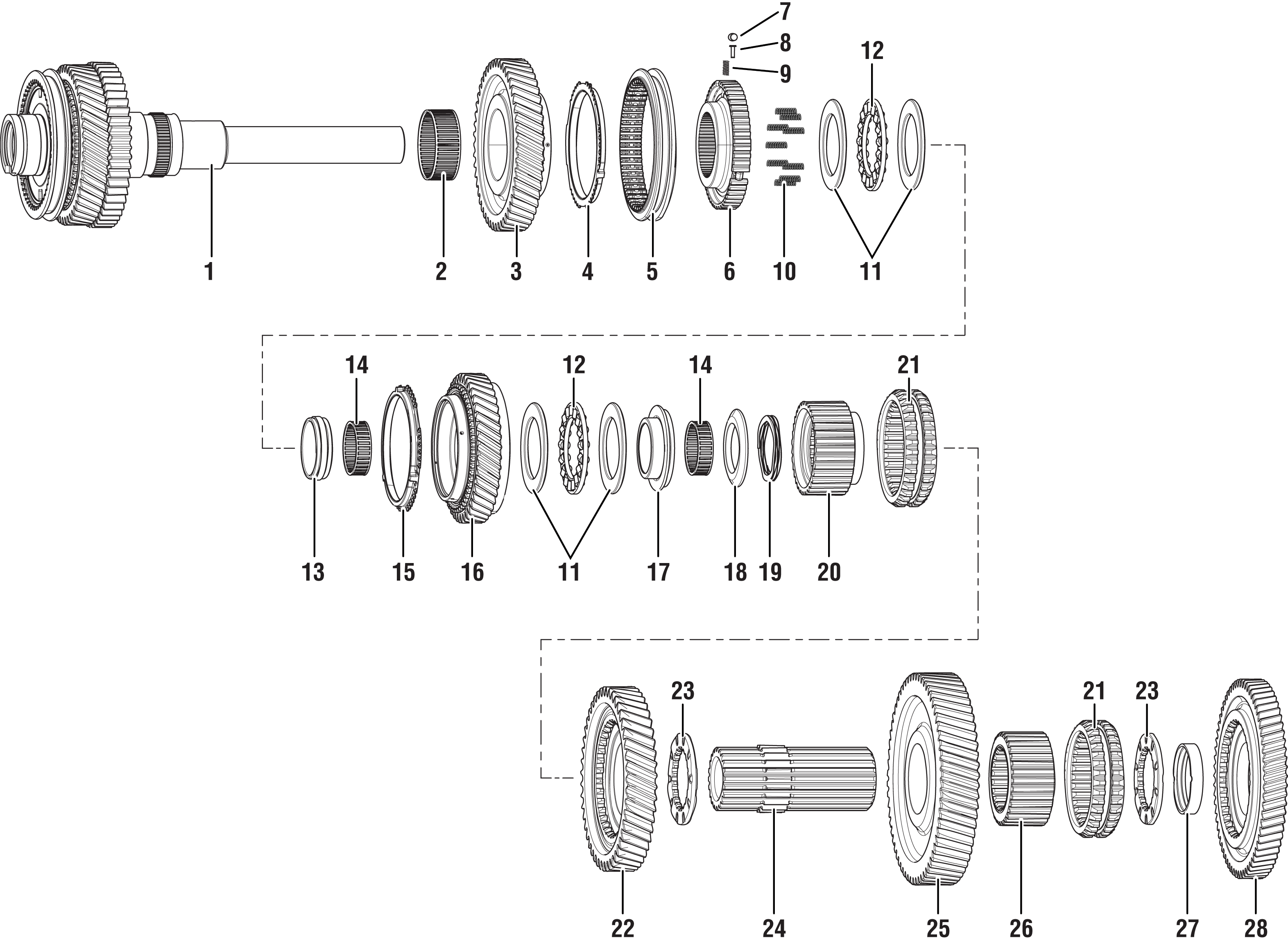 | ||
1. Extension Shaft Sub-Assembly 2. Main Drive Needle Bearing 3. Main Drive Gear Assembly 4. Synchronizer Ring 5. 1st/2nd/3rd/4th Sliding Sleeve 6. Synchronizer Hub 7. Synchronizer Roller 8. Synchronizer Plunger 9. Compression Spring 10. Compression Spring | 11. Thrust Washer (x4) 12. Main Shaft Thrust Bearing 13. Thrust Washer Race 14. Roller Needle Bearing 15. Synchronizer Ring Assembly 16. Welded Main Shaft Gear Assembly 17. Main Shaft Race 18. Spherical Washer | 19. Wave Spring 20. Clutch Hub 21. Main Shaft Sliding Clutch 22. Main Shaft Gear (2nd) 23. Main Shaft Washer 24, Main Shaft 25. Main Shaft Gear (1st) 26. Rev Clutch (1st) Hub 27. Reverse Spacer 28. Main Shaft (Reverse) Gear |
Remove Main Shaft and Both Counter Shaft Assemblies
Install Lifting Bar (RR1114TR) onto the Main Shaft and both Counter Shaft assemblies.
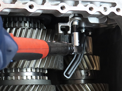
Install both Counter Shaft Lifting Bar Cap Screws (RR1110TR), (8mm x70mm x1.5) and torque to 21-23 Nm (16-18 lb-ft) using a 13 mm hex socket.
Install Main Shaft Lifting assembly Lifting Eye Swivel (RR1111TR), Lifting Mount Nut (RR1112TR), and Lifting Mount Adapter (RR1113TR) and securely tighten.
Attach lifting chain to Main Shaft and both Counter Shaft assemblies and lift the case approximately 1 inch off of table.
Use a dead blow or soft mallet and strike down on the Main Case to free the Main Shaft assembly from the inner race of the Front Input Bearing.
Note: Use extreme care when hitting the Main Case sealing surface to separate the Main Shaft from the Front Input Bearing.
When lifting the Main Shaft and both Counter Shaft assemblies from the Main Case, remove the A-Rail Shift Bar assembly through the MTM opening.
Set the Main Shaft and both Counter Shaft assemblies onto Main/Counter Shaft Staging Block (RR1115TR).
Note: Main/Counter Shaft Staging Block (RR1115tr0 has an open/deeper pocket to accept the longer lower countershaft with the inertia brake splines.
Remove the Main Shaft Lifting assembly, Lifting Eye Swivel (RR1111TR), Lifting Mounting Nut (RR1112TR), and Lifting Mount Adapter (RR1113TR).
Remove both of the Countershaft Lifting Cap Screws.
Remove the Lifting Bar (RR1114TR) from the Main Shaft and both Countershaft assemblies.
Disassembly of Main Shaft Assembly
Rotate both Countershaft assemblies away from the splined positions of the Main Shaft Assembly, while leaving the Countershafts near the end of the Main/Counter Shaft Staging Block (RR1115TR).
Remove Main Shaft Selective Washer.
Remove Reverse Gear Assembly.
Remove Reverse Spacer Assembly.
Remove Main Shaft Washer.
Remove Main Shaft Sliding Clutch Assembly.
Remove Reverse Clutch (1st) Hub Assembly.
Remove Main Shaft Gear (1st) Assembly.
Remove Rear Main Shaft Assembly.
Remove Main Shaft Washer.
Remove Main Shaft Gear (2nd) Assembly.
Remove Main Shaft Sliding Clutch Assembly.
Remove Main Shaft Clutch Hub Assembly.
Remove Main Shaft Wave Spring.
Remove Main Shaft Spherical Washer.
Remove Main Shaft Rear Roller Needle Bearing Assembly.
Remove Main Shaft Race Assembly.
Remove Main Shaft Thrust Washer.
Remove Main Shaft Thrust Bearing.
Remove Main Shaft Thrust Washer.
Remove Main Shaft Welded Gear Assembly.
Remove Main Shaft Synchronizer Ring Assembly.
Remove Main Shaft Upper Thrust Washer.
Remove Main Shaft Thrust Bearing.
Remove Main Shaft Lower Thrust Washer.
Remove Main Shaft Roller Thrust Washer.
Remove Main Shaft 9 Compression Springs.
Remove Main Shaft Synchronizer Ring.
Set Synchronizer ring over the 3 Synchronizer Rollers and Springs, and slowly lift Synchronizer Sleeve, to carefully contain all 3 Synchronizer Springs and Rollers.
Remove Main Shaft Synchronizer Sleeve.
Remove Main Shaft 3 Synchronizer Rollers.
Remove Main Shaft 3 Synchronizer springs and Plunger.
Remove Main Shaft Synchronizer Hub.
Remove Main Shaft forward Synchronizer ring.
Remove Main Shaft Main Drive Gear.
Remove Main Shaft Main Drive Needle Bearing.
The Main Shaft assembly remaining in the picture is the extension Shaft Sub Assembly, and will be serviced as an assembly.
Assemble the Main Shaft
Install Main Shaft Needle Bearing.
Install Main Shaft, Main Drive Gear.
Install Main Shaft Forward Synchronizer Ring.
Install Main Shaft Synchronizer Hub Assembly.
Ensure to line up all 3 notches on Synchronizer Ring with all 3 gaps in Synchronizer Hub Assembly.
Install all 3 synchronizer Springs and Plungers into Synchronizer Hub Assembly openings and use a Pick to fully seat them.
Install Synchronizer Sliding Sleeve on Main Shaft and align splines on the Sliding Sleeve to the splines on the Synchronizer Hub Assembly.
Ensure all 3 Synchronizer Springs and Plungers are fully seated in bores before installing all 3 Rollers.
Lift Synchronizer Sliding Sleeve above neutral position and roll all 3 Synchronizer Rollers in place to fully engage Springs and Rollers.
Set the rear Synchronizer Ring with all 3 notches over the 3 Rollers to contain Rollers from escaping when pushing the Synchronizer Sliding Sleeve down the synchronizer assembly to the neutral position.
Evenly apply downward pressure on Synchronizer Sliding Sleeve until all 3 Rollers have compressed springs in the Synchronizer Hub Assembly and the Synchronizer Sliding Sleeve is in the neutral position.
Install the Main Shaft roller Needle Bearings.
Install all 9 Main Shaft Compression Springs.
Install Main Shaft Trust Washer.
Install Main Shaft Thrust Bearing.
Install Main Shaft Thrust Washer.
Install Main Shaft Synchronizer Ring Assembly with all 3 notches on ring to engage Synchronizer Rollers.
Install Main Shaft Welded Gear Assembly with Synchronizer teeth facing down.
Install Main Shaft Thrust Washer.
Install Main Shaft Thrust Bearing.
Install Main Shaft Thrust Washer.
Install Main Shaft Race Assembly.
Install Main Shaft Rear Roller Needle Bearing Assembly.
Install Main Shaft Spherical Washer.
Install Main Shaft Wave Spring.
Install Main Shaft Clutch Hub Assembly with smooth inner race for Main Shaft Gear (2nd) facing up.
Install Main Shaft Sliding Clutch Assembly (Non-Directional).
Install Main Shaft Gear (2nd) Assembly with Sliding Clutch Teeth down.
Install Main Shaft Washer.
Install Rear Main Shaft Assembly. Ensure Rear Main Shaft is splined to the washer and Clutch Hub.
Install Main Shaft Gear (1st) Assembly with the Clutch Teeth facing up.
Install Reverse Clutch (1st) Hub Assembly (Non-Directional).
Install Main Shaft Sliding Clutch Assembly (Non-Directional).
Install Main Shaft Washer.
Install Reverse spacer assembly (Non-Directional).
Install Reverse Gear Assembly with Clutch teeth down.
Install Main Shaft Selective Washer.
Install and Time Main Shaft and Both Counter Shaft Assemblies
Note: Paint marks are required on Countershafts for alignment to the marks on the Main/Countershaft Staging Block (RR1115TR) when mating both Countershafts to assembled Main Shaft Assembly.
Locate both black paint dots on both Countershaft Main Drive Gears (Top side of bottom gear of Countershafts).
Notice both Countershaft alignment marks on Main/Countershaft Staging Block (RR1115TR).
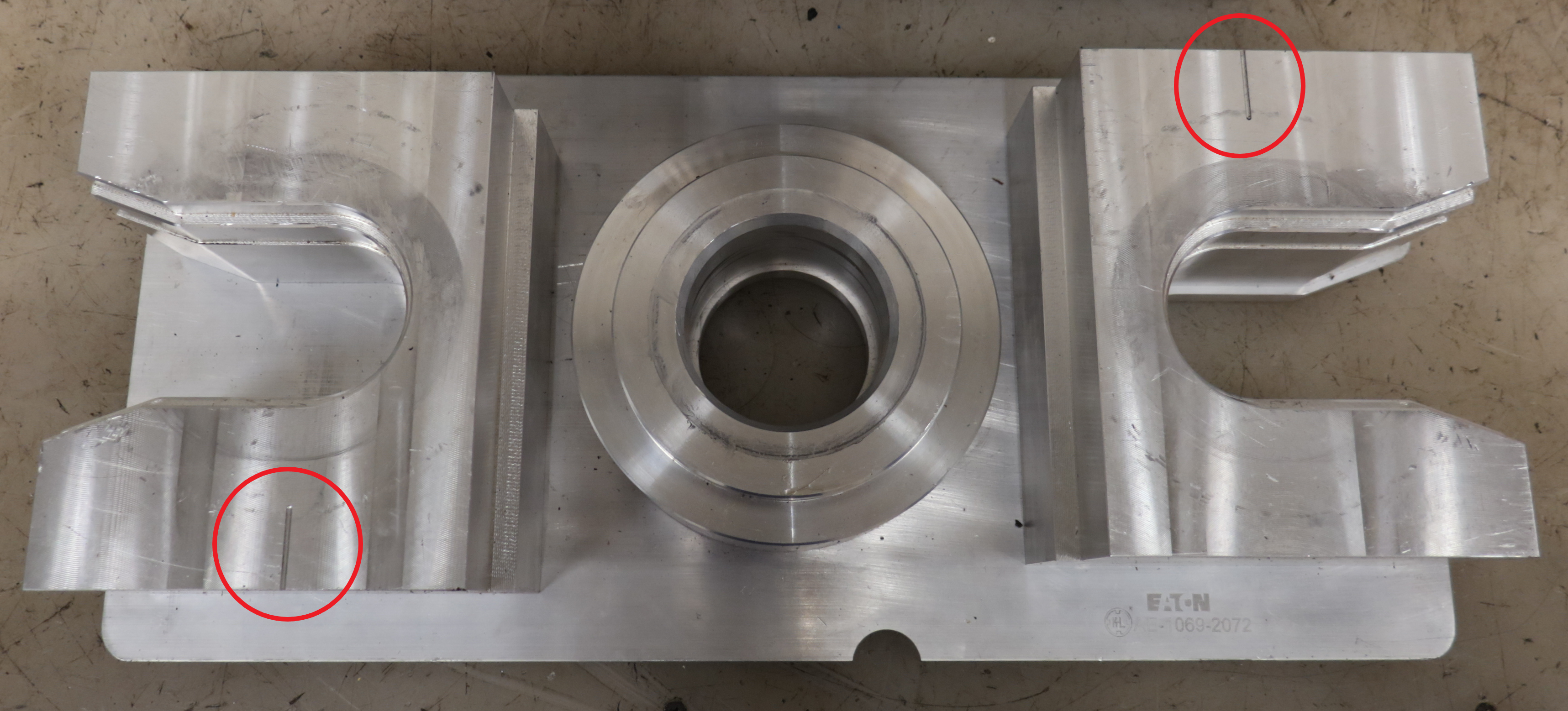
Rotate Lower Countershaft to fully mate gear teeth on both Lower Countershaft and Main Shaft gears, while ensuring both timing marks align with timing marks on the Staging Block.
Note: Ensure to follow angled helical gear teeth from paint marks on gear to alignment marks on the Staging Block.
Rotate Upper Countershaft to fully mate gear teeth on both Upper Countershaft and Main Shaft gears, while ensuring both timing marks align with timing marks on the Staging Block.
Note: Ensure to follow angled helical gear teeth from paint marks on gear to alignment marks on Staging Block.
Install Lifting Bar (RR1114TR) onto the Main Shaft and both Counter Shaft assemblies.
Install both Counter Shaft Lifting Bar Cap Screws (RR1110TR), (8mm x70mm x1.5) and torque to 21-23 Nm (16-18 lb-ft) using a 13 mm hex socket.
Install Main Shaft Lifting assembly Lifting Eye Swivel (RR1111TR), Lifting Mount Nut (RR1112TR), and Lifting Mount Adapter (RR1113TR) and securely tighten.
Lift Main Shaft and Both Counter Shaft Assemblies from staging block.
Ensure that the Input Bearing Capture Plate is installed before setting the Main Shaft and Countershaft assemblies in the Main Case.
Install 4 Cap Screws from Input Shaft Cover and torque to 21-25 Nm (16-19 lb-ft).
Position Main Shaft and Both Counter Shaft Assemblies over the Main Case.
Install Countershaft Pilot Guide Upper (RR1100TR) on to shaft.
Install Countershaft Pilot Guide Lower (RR1099TR) on to shaft.
Install Shift Rail A Yoke on to Rail A synchronizer sleeve through the MTM opening while lowering the Main Shaft and both Counter Shaft Assemblies into the Main Case.
Ensure proper alignment of both Counter Shafts into bearings and Rail A Shift Yoke shaft is in Main Case opening.
Slowly set assembly until both Countershafts and Main Shaft are fully seated into the inner race of the input bearing using a Dead Blow hammer on top for main shaft lifting eye assembly.
Measure and Adjust the Main Shaft End-Play
Note: The Main Shaft Selective Washer is available in 4 thicknesses: 6.525 mm (0.257 in), 6.875 mm (0.271 in), 7.225 mm (0.285 in), or 7.575 mm (0.298 in).
Place Intermediate Housing on a bench and support housing on the Oil Pump Assembly surface with Input Bearing Guide (RR1095TR).
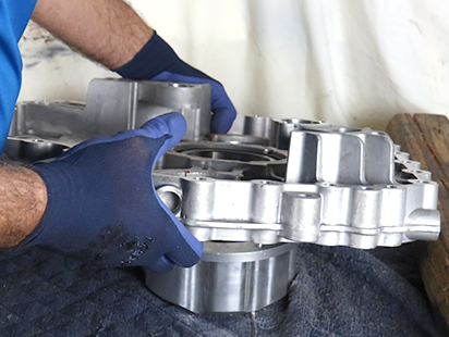
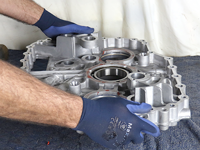
Place Input Shaft Bearing Removal and Installation Tool (RR1075TR) and Universal Driver Handle (OE8044-T0) onto Main Shaft Bearing.
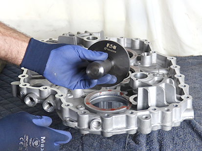
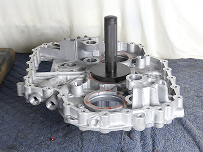
Use a hammer to drive the Main Shaft Bearing out of Intermediate Housing.
Notice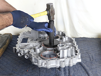
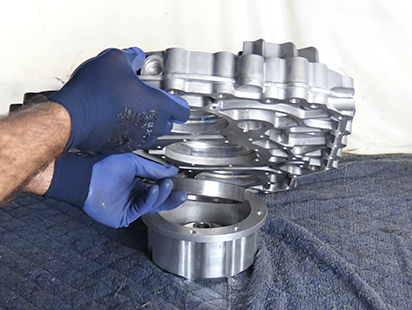
Remove Main Bearing O-Ring from Intermediate Housing.
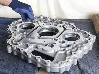
Install the Intermediate Housing to the Main Housing and install 4 long MTM mounting bolts (M10x60x1.5). Torque all 4 bolts to 13-15 NM (10-11 Lb-ft).
Remove Main Shaft selective washer to measure Main Shaft End-Play.
Make note of what size selective washer is removed. The selective washer part number is stamped onto the selective washer.
Pay close attention to the 3 cutaway slots on the Main Bearing shoulder of the Intermediate Housing. Ensure the Dial Indicator shaft will not align to the 3 cutaway slots in the Main Housing when mounting the Main Shaft End-Play measurement tool.
Install the Main Shaft End-Play measurement tool assembly with Dial Indicator onto the Intermediate Housing.
Install 4 Oil Pump mounting cap screws to secure Main Shaft End-Play measurement tool to Intermediate Housing. Torque all 4 oil pump bolts to 21-23 Nm (19-18 Lb-ft).
Install Main Shaft compression tools (RR1109TR Sleeve and RR1108TR Tension Nut) and tighten nut to fully compress Main Shaft and torque to 13-15 Nm (10-11 Lb-ft).
Slide dial indicator block to inward slot position and tighten sliding block cap screw. Zero dial indicator on spacer plate (RR1106TR).
Slide dial indicator block to outward slot position and tighten block cap screw. Measure Main Shaft End-Play reading by touching the dial indicator shaft on Main Bearing shoulder of the Intermediate Housing. Record reading in table.
Reference the Selective Main Shaft Washer Reference Chart and compare Recorded End-Play to reading in table.
Main Shaft Selective Washer Reference Chart
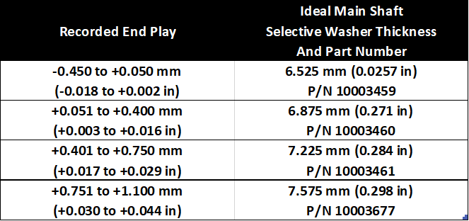

Install the correct Main Shaft Selective washer as directed by the “Main Shaft Selective Washer Reference Chart” above.
Install the Main Shaft bearing O-ring into the Intermediate Housing.
Locate the bearing lock window in the Intermediate Housing.
Set the Main Shaft Bearing lock pin to align with the Intermediate Housing bearing lock window and the ensure the roll pin is in the upward position.
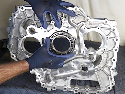
Support the Intermediate Housing using Input Bearing Guide (RR1095TR).
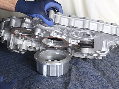
Using Bearing Installer (RR1077TR) and Universal Handle (OE8044-TO) drive the Bearing into the housing until the bearing is fully seated.
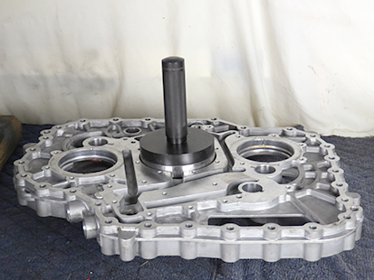
Install Intermediate Housing Assembly
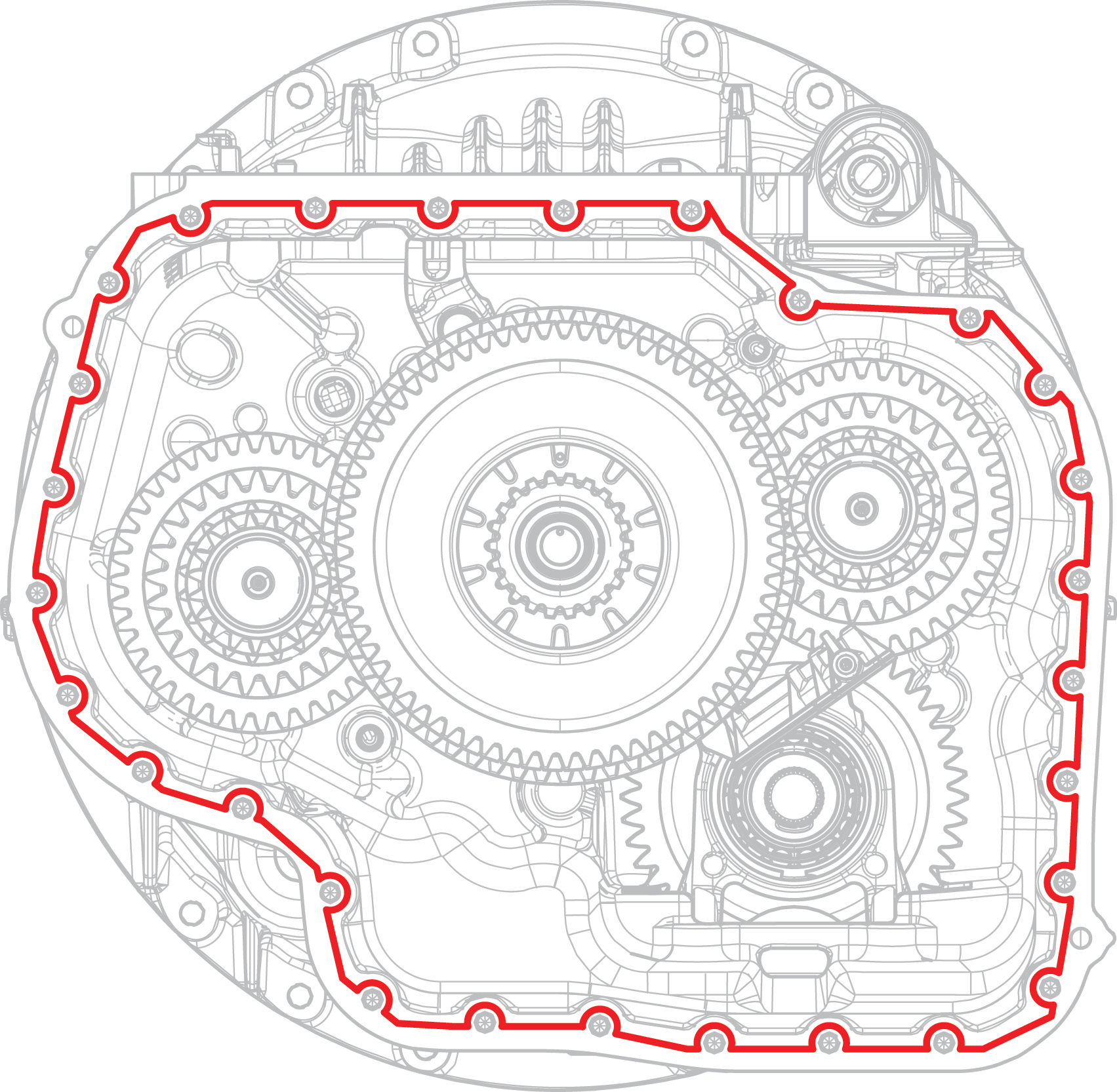
Apply Gasket Sealant with a bead width of 1.4-2.4 mm (0.055-0.094 inch) to the transmission Main Housing sealing surface following the pattern below.
NoticeNote: Parts must be assembled within 30 minutes of applying Gasket Sealant.
Install the Intermediate Housing Assembly.
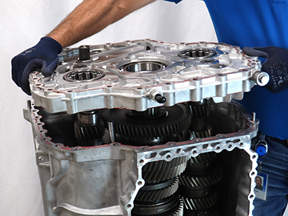
Install the Rear Upper Main Shaft lube tube into the Intermediate Housing.
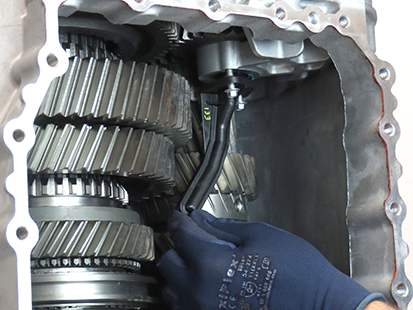
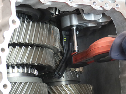
Install both 8 mm cap screw and torque to 8-10Nm (6-13 lb.-ft).
Install the Oil Pump Assembly
Install O-ring to the Oil Pump/Range Spacer.
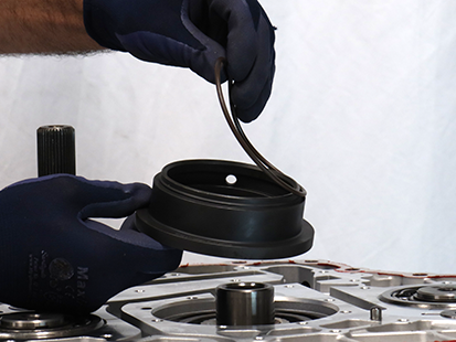
Install Oil Pump/Range Spacer with O-ring and align tab with groove in Intermediate Housing.
CautionNotice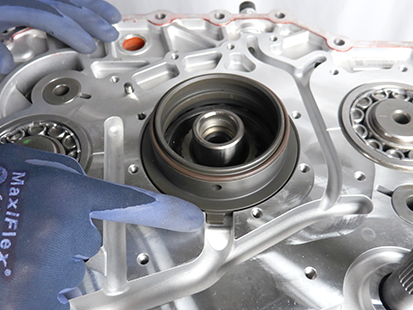
Install the Oil Pump Assembly on the Intermediate Housing.
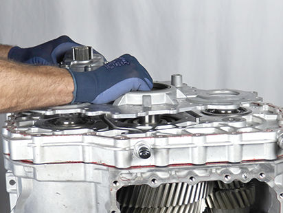
Press Oil Pump Assembly to ensure it sits flat on Intermediate Housing sealing surface.
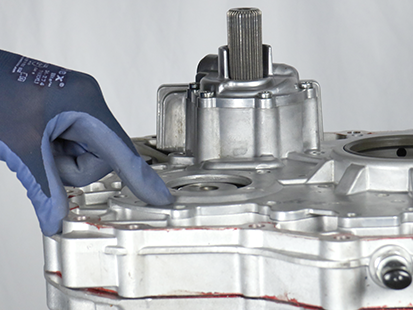
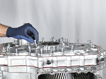
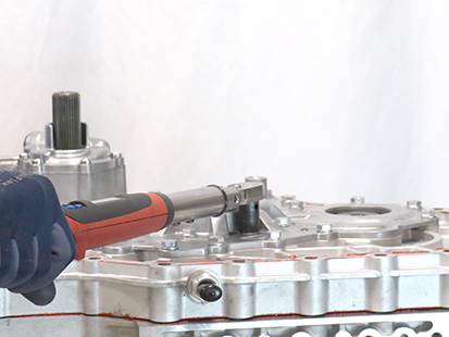
Install 30 Oil Pump Assembly 13 mm cap screws and torque to 21–23 Nm (16–18 lb–ft) in a criss-cross pattern.
Install the Rear Housing
Clean the sealing surfaces on the transmission Intermediate Housing and Rear Housing with gasket remover and a plastic scraper. Let air dry then wipe with a clean dry cloth.
NoticeInspect threaded bolt holes for debris and clean if necessary.
Apply Gasket Sealant with a bead width of 1.4-2.4 mm (0.055-0.094 inch) to the transmission Intermediate Housing sealing surface following the pattern below.
NoticeNote: Parts must be assembled within 30 minutes of applying Gasket Sealant.
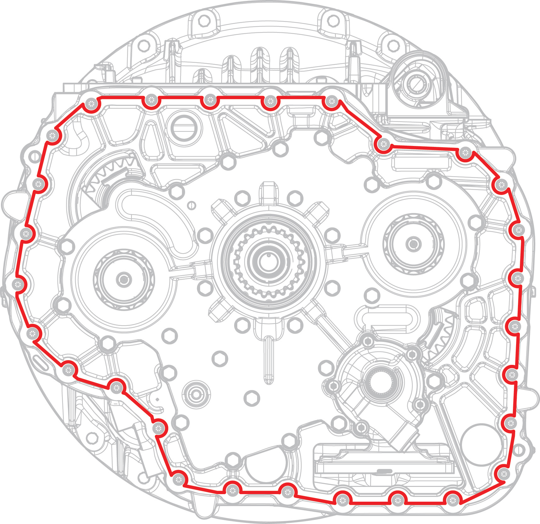
Install and hand tighten 2 Rear Housing Alignment Pins (RR1090TR) 180-degrees apart.
Caution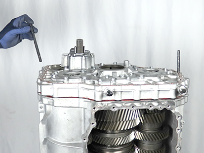
Lift and install the Rear Housing Assembly on to the Main Housing.
WarningNoticeNote: Align the Rear Housing to the alignment pins and align Shift Rail E into the Main Housing during installation.
Note: Rotate Output Shaft to align gearing and allow Rear Housing Assembly to fully seat on Main Housing.
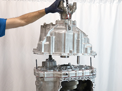
Install the 28 Rear Housing 16 mm cap screws.
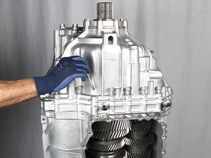
Torque the 28 Rear Housing 16 mm cap screws to 44.5 - 51.5 Nm (33-38 lb-ft) in a criss-cross pattern.
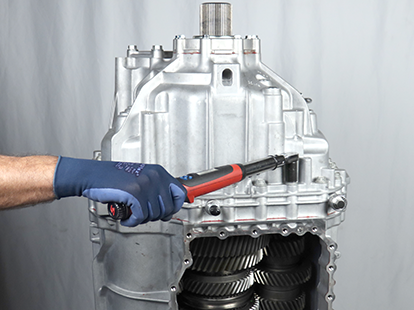
Lift transmission horizontally onto a bench.
WarningNoticeInstall Rail E shift range block using 8mm hex key and torque to 21.0 - 25.0 Nm (16-19 lb-ft).
