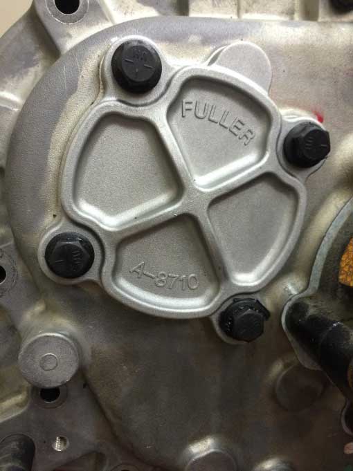
Auxiliary Section Assembly and Installation
Special Instructions
None
Special Tools
PVC pipe (4-3/8" tall x 4" diameter)
Component Identification
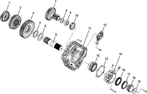 | |
1. Auxiliary Drive Gear 2. Synchronizer Assembly 3. Reduction Gear 4. Washer 5. Spacer 6. Auxiliary Main Shaft 7. Auxiliary Counter Shaft 8. Spacer 9. Bearing 10. Race | 11. Auxiliary Case 12. Auxiliary Counter Shaft Cover 13. Auxiliary Main Shaft Bearing Set 14. Gasket 15. Bearing Cover 16. Seal 17. Dust Shield 18. Speed Rotor Assembly 19. Output Yoke Retainer Flange |
Auxiliary Section Assembly
Place Output Shaft on bench with yoke end facing up.
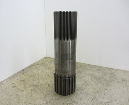
Install the stepped washer onto the backside of the Auxiliary Reduction Gear.
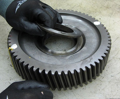
Install the splined spacer into the clutching teeth of the Auxiliary Reduction Gear.
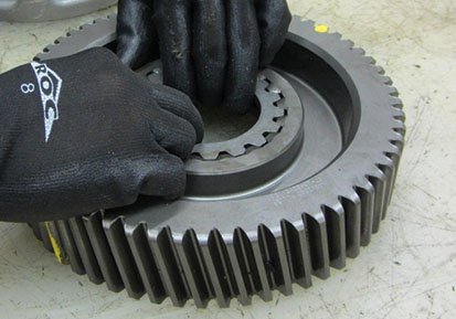
Install the Auxiliary Reduction Gear onto the Output Shaft with the clutching teeth facing down.
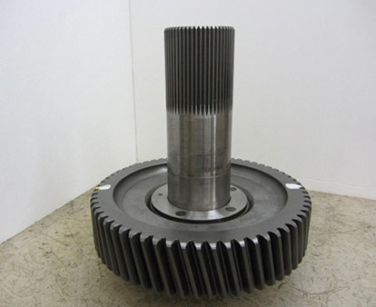
Mark any two teeth 180 degrees apart on the Range Reduction Gear using a highly visible dye.
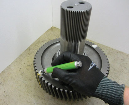
Place the inner bearing (longer rollers) tapered side up over the Auxiliary Main Shaft.
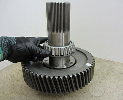
Drive the bearing down to the Auxiliary Reduction Gear using the Output Shaft Bearing Driver.
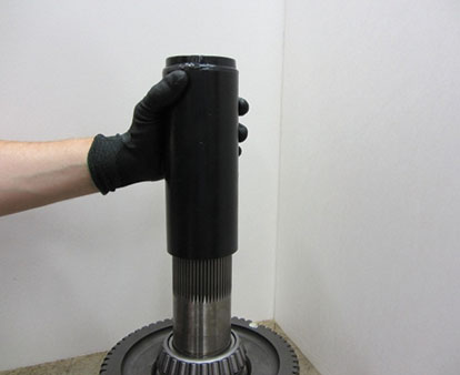
Slide the bearing spacer down on top of the inner bearing.
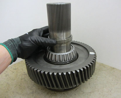
Auxiliary Counter Shaft Installation and Timing
If previously removed, install the bearings onto the rear of each Counter Shaft.
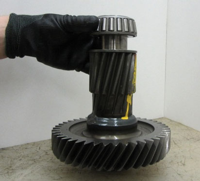
On each low range gear of the Auxiliary Counter Shaft assemblies, use a highly visible color of dye to mark the valley of the tooth stamped with an “O” for timing purposes.
Note: The “O” may be behind the washer and bearing on the rear of the Counter Shaft Gear.
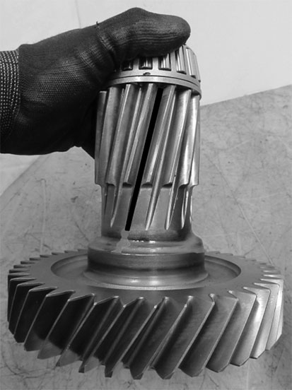
Place the Auxiliary Main Shaft positioning cone around the splines of the shaft, set the Main Shaft upright with the Synchronizer facing down.
Note: Cone size must be 4-3/8" tall with a 4" inner diameter. PVC pipe is recommended.
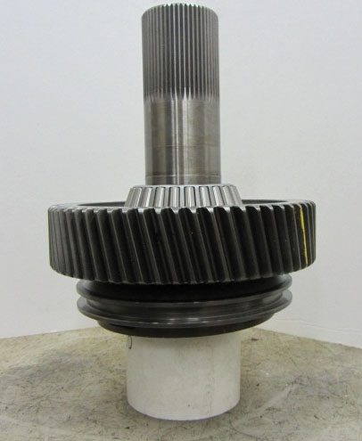
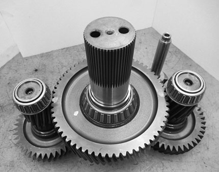
Move the upper and lower Counter Shafts into place on the Range Reduction Gear lining up the timing marks previously made.
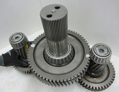
Position the Range Shift Yoke on the Range Synchronizer Sliding Clutch with the shaft aligned above the lower Counter Shaft.
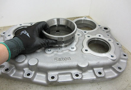
Install the double bearing race into the Auxiliary Case with the race flange out.
Before installing the Main Case, remove excess RTV sealant from the mating surfaces of the Auxiliary Case and Main Case.
Place the Auxiliary Case over the Main Shaft/Counter Shaft assembly.
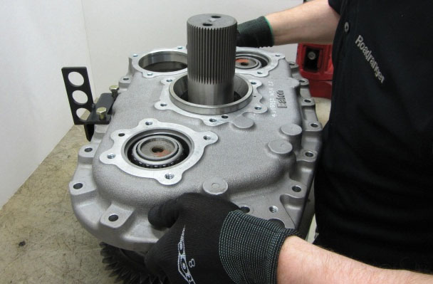
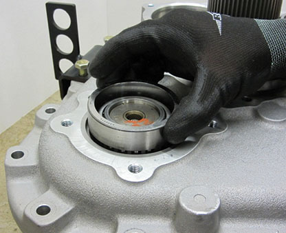
Install the upper and lower Counter Shaft Rear Bearing Races into the Auxiliary Case.
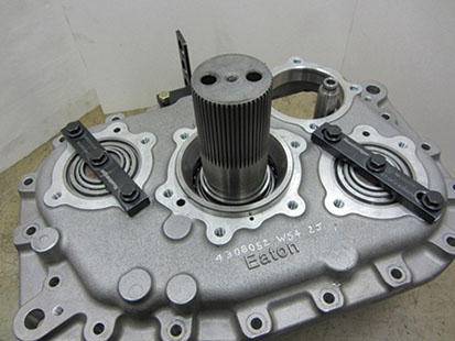
Install the Auxiliary Counter Shaft Support Straps to hold the Counter Shafts in place.
Note: Hold the Counter Shafts from spinning while tightening Auxiliary Counter Shaft Support Straps, failure to do this could allow Counter Shafts to come out of time with the Range Reduction Gear.
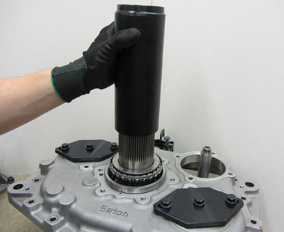
Place the outer Auxiliary Shaft Bearing over the shaft with the tapered side down (short rollers), drive into place using the Output Shaft Bearing Driver.
Install the Output Shaft Bearing Cover and gasket.
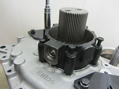
Apply lube to the o-ring on the Range Shift Fork Shaft and Range Cylinder O-ring, install the Range Cylinder.
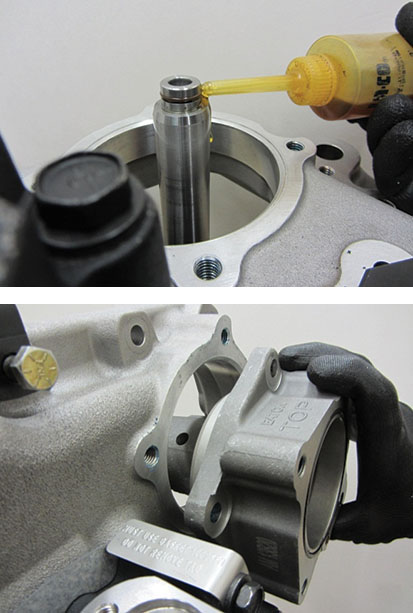
Install the Range Cylinder bolts; torque to 45–55 lb-ft.
Apply lube to the Range Piston O-ring, install piston into the Range Cylinder. Install the Range Piston cap screw and torque to 20–25 lb-ft.
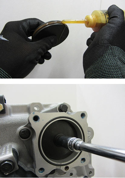
If the Main Case gearing does not need to be serviced, attach the Auxiliary Section Lifting Bracket to the top of the Auxiliary Case.
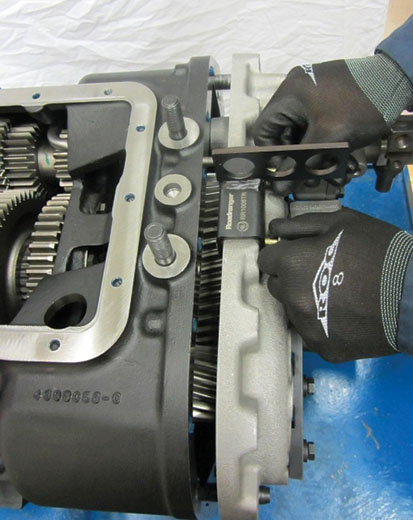
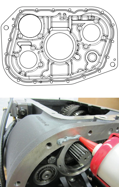
Apply Loctite 5810F RTV or anaerobic 5188 sealant to the Auxiliary Case to Main Case joint, using an 1/8" bead apply the sealant inward of all cap screws holes.
Note: Follow the pattern in the image below. Parts must be assembled within 30 minutes of applying sealant. The area must be clean of contaminants, ensure surfaces are adequately prepped.
Install the Auxiliary Case assembly onto the Transmission Main Case dowel pins. Using the Output Shaft, wiggle the Auxiliary Case forward until it is as far forward as possible. Remove the Auxiliary Section Lifting Bracket.
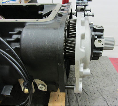
Push Auxiliary Section flush with the Transmission Main Case and install cap screws. Torque cap screws to 40–45 lb-ft.
Note: If Auxiliary Case does not come flush with the Transmission Main Case with minimal force this could indicate an issue with Auxiliary gearing timing.
Note: If Auxiliary Section Bearings or gearing were replaced then the Auxiliary Counter Shaft shimming procedures will need to be followed.
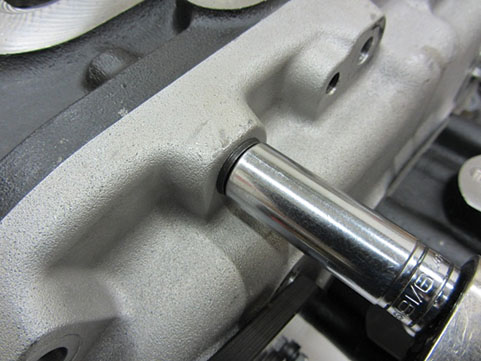
Auxiliary Section Installation In Chassis
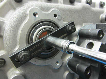
Ensure that the Auxiliary Counter Shaft Support Straps are still installed and all three cap screws are snug.
Apply Loctite 5810F RTV or anaerobic 5188 sealant to the Auxiliary Case to Main Case joint, using an 1/8" bead apply the sealant inward of all cap screws holes.
Note: Follow the pattern in the image below. Parts must be assembled within 30 minutes of applying sealant. The area must be clean of contaminants, ensure surfaces are adequately prepped.

Using a transmission jack and support bracket, lift the Auxiliary Case assembly and line up the two holes in the Auxiliary Case with the Transmission Main Case alignment pins. Push the case forward toward the Transmission Main Case.
Note: Verify the Auxiliary Counter Shafts are still timed to the Auxiliary Reduction Gear before installing. This will allow for easier installation and timing to the Auxiliary Drive Gear.
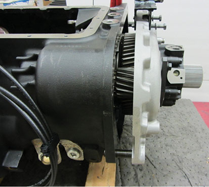
Once the Auxiliary Case is pushed as far into the Transmission Main Case as possible, remove the Auxiliary Section Lifting Bracket. Loosen the Auxiliary Counter Shaft Support Strap cap screws and fully seat the Auxiliary Case to the Transmission Main Case.
Note: Fully seating the Auxiliary Section to the Transmission Main Case should take light force; do not draw it in with bolts. If the Auxiliary Section will not come flush with the Transmission Main Case, a timing issue with the Auxiliary Section gearing may be the cause.
Install the 16 cap screws that fasten the Auxiliary Section to the Transmission Main Case. Torque bolts to 35–45 lb-ft.
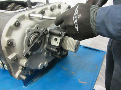
Auxiliary Counter Shaft Shimming
Remove the Auxiliary Counter Shaft Support Straps and install a 0.100" shim between the cover and Auxiliary Counter Shaft. Use two of the Counter Shaft Bearing Cover bolts and torque bolts to 7 lb-in. Spin the Output Shaft multiple times to assist in seating the bearing races. Ensure cap screws are still torqued at 7 lb-in.
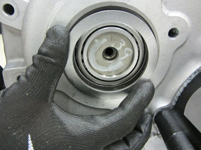
Using feeler gages, measure the gap between the Auxiliary Counter Shaft Covers and the Auxiliary Case. Use multiple positions closest to the cap screws.
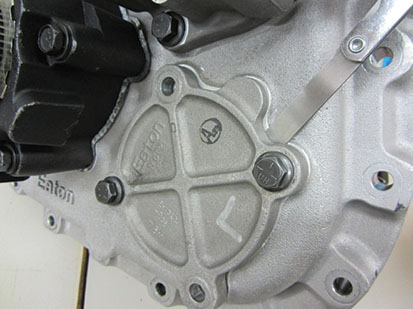
Subtract the thickness of feeler gauges needed to fit in between the Auxiliary Case and Auxiliary Counter Shaft Covers from 0.100". Use that number to pick a shim that will allow for end-play of within 0.001"–0.005".
Note: Example: 0.042" of feeler gauges fit in between Auxiliary Case and the Auxiliary Counter Shaft Bearing Cover. Subtract 0.042" from 0.100" which equals 0.058". A shim of 0.052"–0.055" would be required for the 0.003"–0.005" end-play. (If the required thickness shim does not exist, use the closest undersized shim.)
Install required shim into bearing bore, apply Loctite 5810F RTV or anaerobic 5188 sealant to the Counter Shaft Bearing Cover position on the Auxiliary Case and install cover. Torque cap screws to 30–35 lb-ft.
Note: Follow the pattern in the image below. Parts must be assembled within 30 minutes of applying sealant. The area must be clean of contaminants, ensure surfaces are adequately prepped.
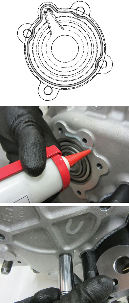
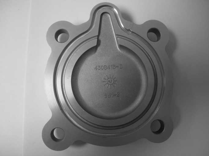
New Style Auxiliary Countershaft cover with O-ring Installation
Verify that the O-ring groove is clean of debris.
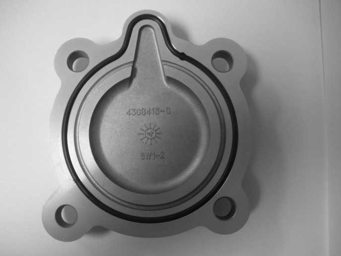
Start at the top by the oil passage and press the O-ring in the groove around the cover. Working it in evenly on each side until the O-ring is fully seated.
Note: A small amount of transmission oil may be used if needed to assist on the installation of the O-ring.
Install the Countershaft Cover on the Auxiliary Section. Torque cap screws 30-35 lb-ft.
