Auxiliary Section Removal and Disassembly
Special Instructions
None
Special Tools
- RR1006TR - Auxiliary Section Hanger
- RR1002TR - Counter Shaft Support Tools
Component Identification
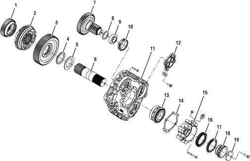 | |
1. Auxiliary Drive Gear 2. Synchronizer Assembly 3. Reduction Gear 4. Washer 5. Spacer 6. Auxiliary Main Shaft 7. Auxiliary Counter Shaft 8. Spacer 9. Bearing 10. Race | 11. Auxiliary Case 12. Auxiliary Counter Shaft Cover 13. Auxiliary Main Shaft Bearing Set 14. Gasket 15. Bearing Cover 16. Seal 17. Dust Shield 18. Speed Rotor Assembly 19. Output Yoke Retainer Flange |
Output Yoke Removal
Remove the two bolts that fasten the Output Yoke to the Output Shaft.
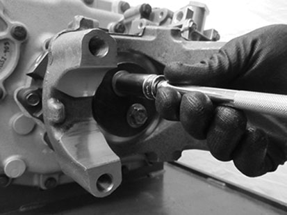
Remove the Output Yoke from the Output Shaft, a maul or hammer may be required to apply force to the yoke for removal.
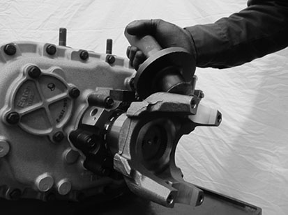
Auxiliary Section Removal
Remove both Auxiliary Counter Shaft Bearing Covers.
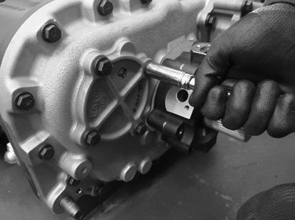
Install Auxiliary Counter Shaft Support Straps using bolts 3 out of the 4 bolts for the Auxiliary Counter Shaft Bearing Covers.
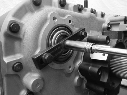
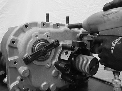
Remove the 19 bolts that fasten the Auxiliary Section to the Transmission Main Case.
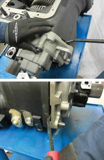
Using prying points, separate the Auxiliary Section from the Transmission Main Case enough to fit the Auxiliary Section Lifting Bracket into place.
Using an overhead crane or hoist, remove the Auxiliary Section with the Auxiliary Section Lifting Bracket.
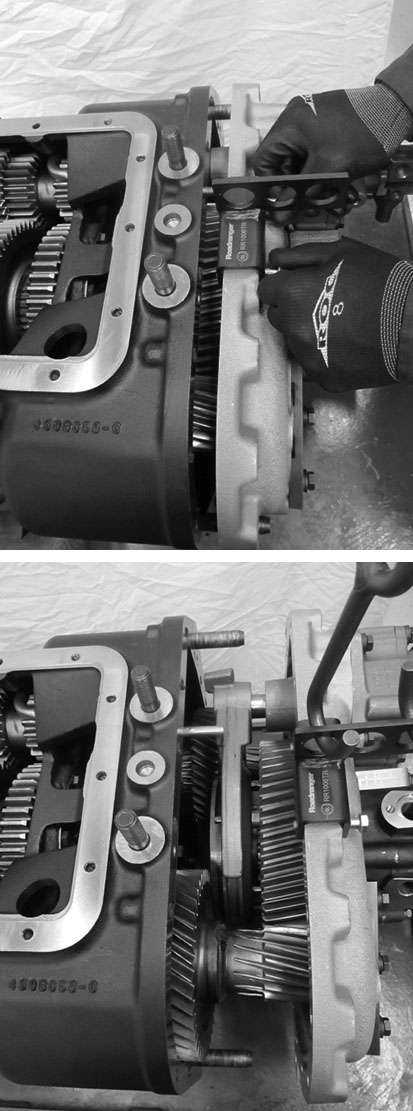
Auxiliary Section Disassembly
Remove the six cap screws that fasten the Output Shaft Bearing Cover to the Auxiliary Section, remove the Output Shaft Bearing Cover.
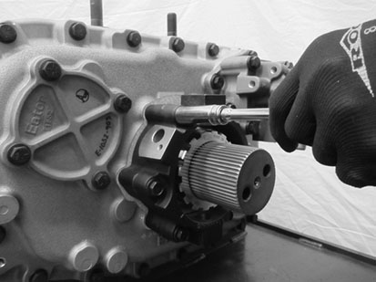
Remove the cap screws that fasten the Range Cover to the Range Cylinder. Remove the Range Cover.
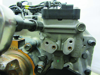
Remove the single cap screw that fasten the Range Piston to the Range Shift Yoke Bar.
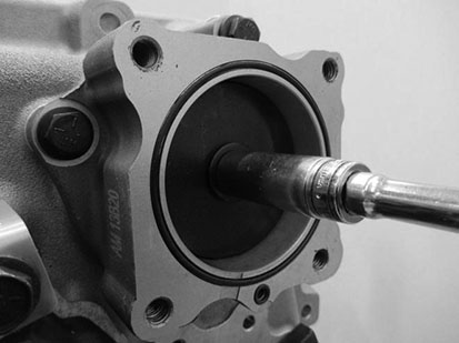
Remove the four cap screws fastening the Range Cylinder to the Auxiliary Section. Remove the Range Cylinder assembly.
Caution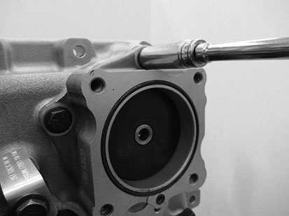
Place the Auxiliary Section on a bench with the gearing facing down; remove the Auxiliary Counter Shaft Support Straps, using a hand maul drive the Output Shaft out of the case.
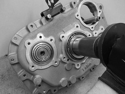
As the Auxiliary Main Shaft is driven out, remove the Synchronizer assembly and the Range Yoke.
Remove the bearing cup and outer spacer from the Auxiliary Case bore.
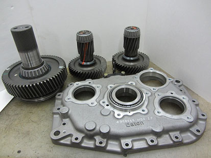
Using the front face of the low range gear as a base, press the Output Shaft through the gear and bearing. Remove the bearing and washer from the hub of the Auxiliary Reduction Gear.
Note: If reusing the bearing set, the tapered roller bearings are specific to each side of the race.
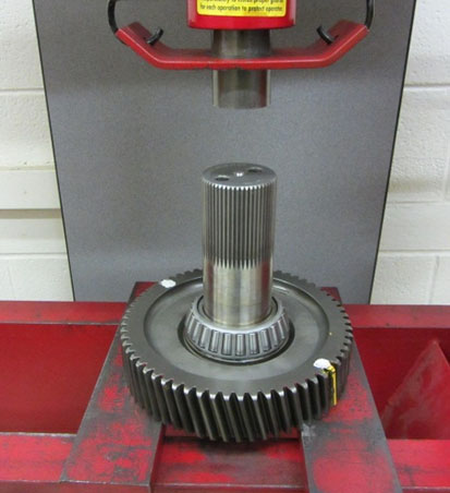
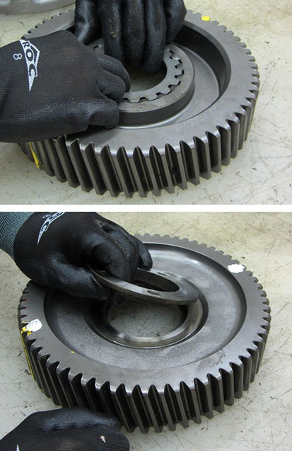
Remove the splined spacer and stepped washer from the Auxiliary Reduction Gear.
Range Synchronizer Disassembly
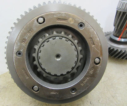
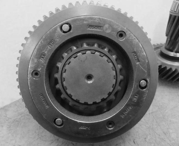
Remove the Range Synchronizer from the Output Shaft.
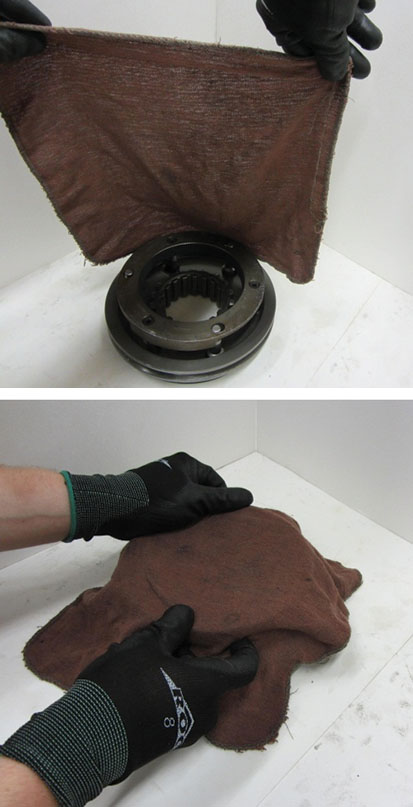
Place the Low Range Synchronizer on a bench with the larger ring facing down, (place a shop towel over the assembly to avoid losing any springs) pull the High Range Synchronizer from the Blocker Ring
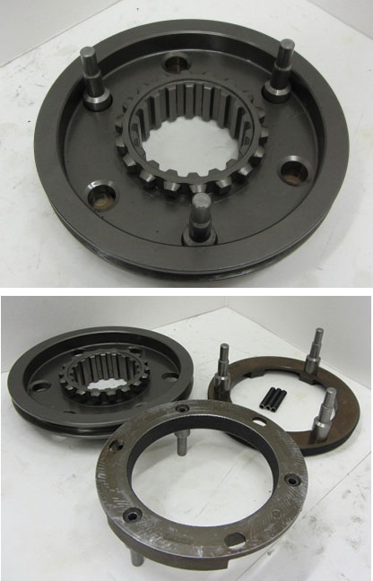
Remove the Sliding Clutch from the pins of the Synchronizer Ring.
Range Synchronizer Assembly
Install the Sliding Clutch on the Blocker Pins with the recessed side up.
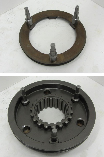
Install the three springs into the bores of the High Range Synchronizer Ring.
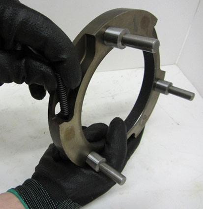
Place the High Range Synchronizer Ring over the Blocker Pins of the Low Range Synchronizer, seating the springs against the pins.
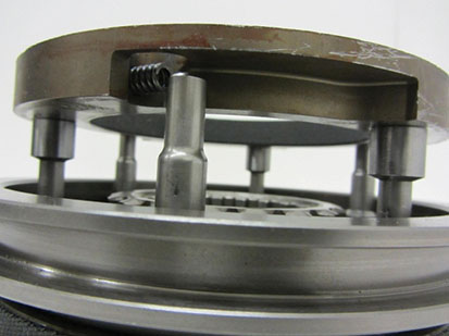
Apply downward pressure to the High Range Synchronizer Ring while twisting counterclockwise to compress the springs and fully seat the ring on the Blocker Pins of the Low Range Synchronizer.
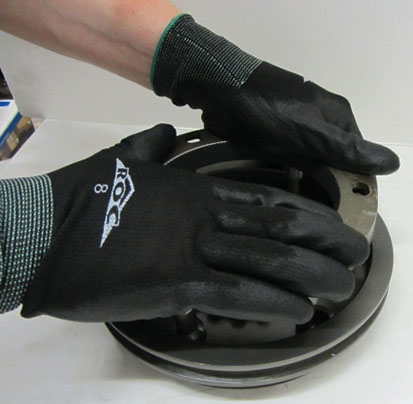
Install the Synchronizer assembly on the splines of the Auxiliary Main Shaft with the Synchronizer seated against the Range Reduction Gear.
