Electronic Clutch Actuator (ECA)
Special Instructions
If vehicle is equipped with an 8-bolt PTO, removal may be required prior to removing the ECA. Follow PTO manufacturer’s guidelines for removal.
Special Tools
- Basic hand tools
Component Identification
 |
1. ECA 2. ECA Cap Screw |
Electronic Clutch Actuator (ECA) Removal
Removal
Disconnect the negative battery cable.
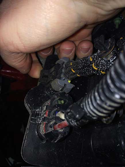
Disconnect the 8-way and 3-way connectors from the ECA.
Note: Some models do not use a shield.

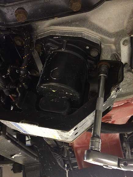
Remove the 4 cap screws from the ECA Shield and remove shield.

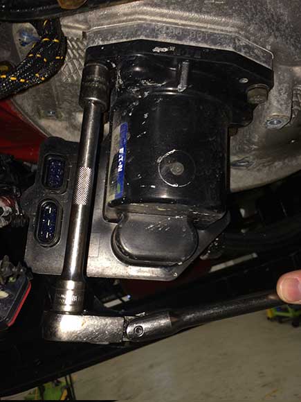
Remove the 4 cap screws from the ECA mounting flange.

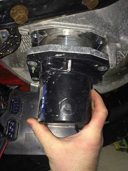
Remove the ECA.
Note: The ECA has an alignment pin that requires the unit to be rotated to exit the Clutch Housing bore.
Note: If ECA will not slide from the Clutch Housing after all the fasteners are removed, use the available pusher holes found on both sides of the ECA casting. Place the included jackscrews into the holes. Turn each jackscrew until it touches. Next, turn the upper jackscrew 1 turn; then rotate the lower jackscrew 1 turn. Continue until the ECA is fully displaced from the bore.

Electronic Clutch Actuator Installation
Install the ECA into the Clutch Housing bore. Align it with the lower Cross-Shaft.
Note: The ECA will have to be rotated to align with the slot in the Clutch Housing.
Note: Ensure you rotate the Release Yoke as close to the Case Dowel in the Clutch Housing prior to mating with the Cross-Shaft. This allows the Release Yoke to clear the Release Bearing during installation.

Install the 4 cap screws from the ECA mounting flange. Tighten them to 35–45 lb-ft (47–61 N•m).
Note: The cap screws for the ECA are longer than the ECA Bracket cap screws.
Note: Ensure the ECA does not bind on the Cross-Shaft by snugging all cap screws before tightening to the specified torque.

If applicable, install the 4 cap screws for the ECA Shield. Tighten them to 35–45 lb-ft (47–61 N•m).

Apply NyoGel to terminals and reconnect the 8-way and 3-way connectors to the ECA.
Note: Apply just enough material to cover the end of the terminal.
Note: Use only Eaton lubricant part number 5564527 (Nye Lubricants NYOGEL 760G. For MSDS safety or other information see www.nyelubricants.com.)

Reconnect the negative 12-volt battery cable.
If previously removed, install the 8-bolt PTO after ECA installation. Follow the PTO manufacturer’s guidelines for installation instructions.