Oil Pump and Lube Tube Installation
Special Instructions
None
Special Tools
None
Component Identification
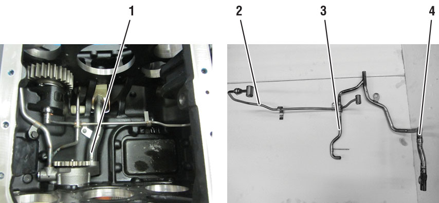 |
1. Suction Strainer 2. Reverse Idler Feed Tube 3. Auxiliary Feed Tube 4. Main Case Feed Tube |
Oil Pump Installation
Clean any debris from the Transmission Main Case before assembly.
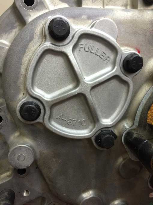
Install the Oil Pump Port Cover and new gasket on the side of the Transmission Main Case; torque cap screws to 8–12 lb-ft.
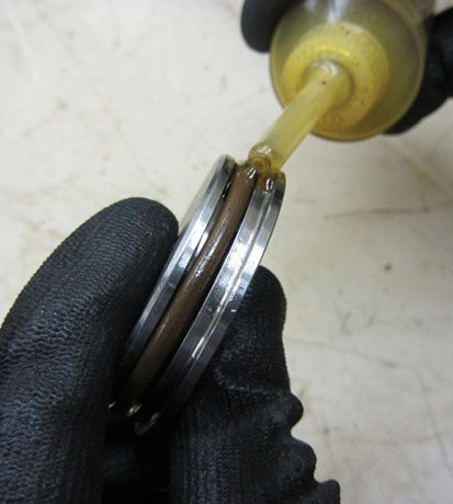
Apply oil or assembly lube to the O-ring on the Oil Pump Cover. Install into the front of the Transmission Main Case.
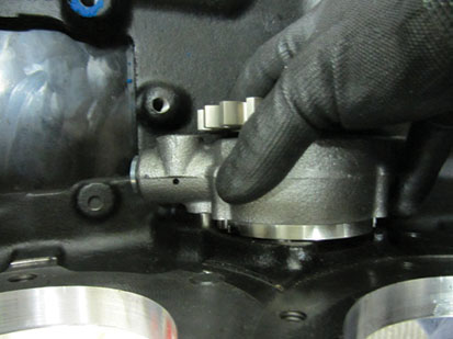
Install the Oil Pump into the Transmission Main Case; torque cap screws to 8–12 lb-ft.
Lubrication Tubes Installation
Install both Reverse Idler Retaining Clips onto on the Lube Tube connection points.
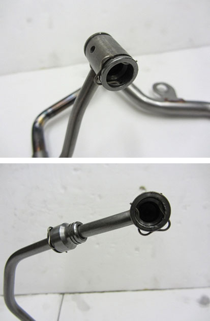
Install the short upper Reverse Idler Tube onto the Reverse Idler Tube assembly.
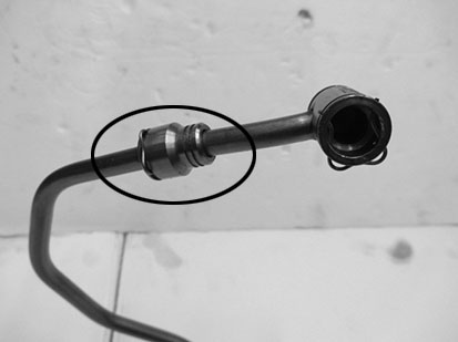
Install the Suction Strainer into the Transmission Main Case, push the tube into the Oil Pump until the tab is flush against the Oil Pump.
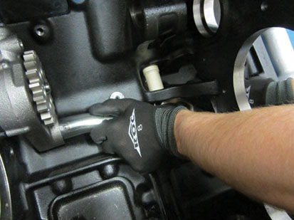
Install the Main Feed Tube into the Transmission Main Case.
Note: The tube needs to be rotated through the Shift Bar Housing opening while going through the intermediate wall, then rotated into place to line up with the Oil Pump.
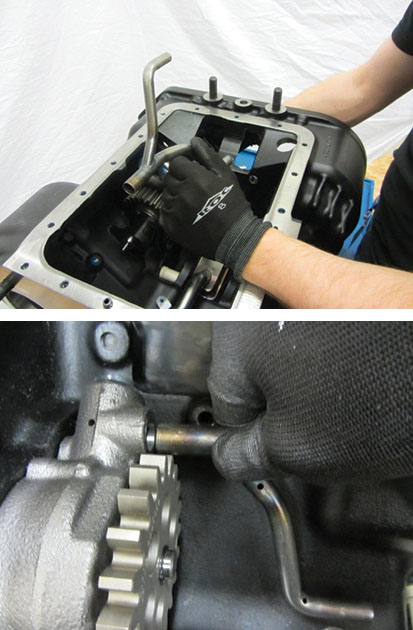
Install the Reverse Idlers Feed Tube into the Transmission Main Case.
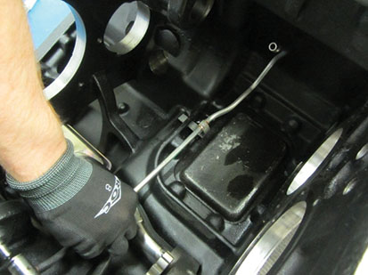
With the Reverse Idler Feed Tube in place, bend the metal tab around the webbing at the 8-bolt PTO cover opening to secure the tube.
Connect the Reverse Idlers Feed Tube to the lower Reverse Idler.
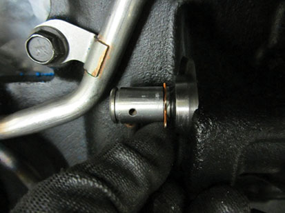
Install the Auxiliary Drive Gear Feed Tube into the Transmission Main Case, connect the Reverse Idlers Feed Tube, Main Feed Tube and Auxiliary Drive Gear Feed Tube together and install the retaining clip.
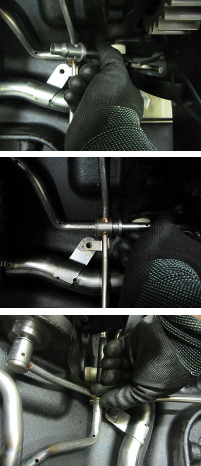
Install the cap screw that secures the Suction Strainer, Reverse Idlers Feed Tube and Auxiliary Drive Gear Feed Tube together.
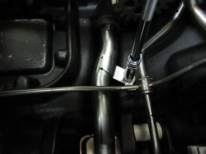
Install the two cap screws securing the Main Feed Tube to the Transmission Main Case.
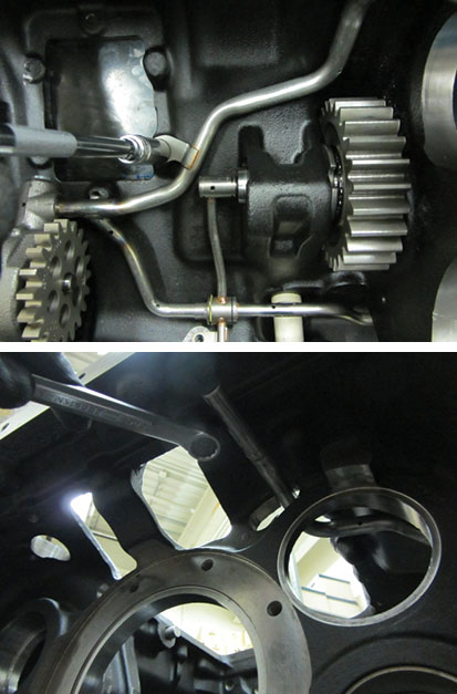
Main Case Gear Timing and Assembly
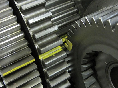
Using the “O” stamped onto the rear of the Main Case Counter Shafts, mark the corresponding tooth on the Main Drive Gear set (front gear) with highly visible ink or dye.
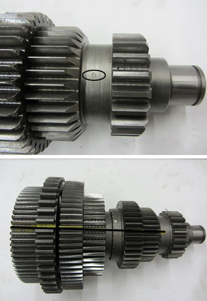
Mark two adjacent teeth on the Main Drive Gear with highly visible ink or dye, then mark two more teeth 180 degrees apart.
Note: There should be an equal number of teeth in between both marks, counting both directions around the gear.
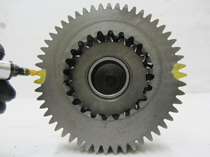
Main Case Counter Shaft Installation
Using a J-hook, install the lower Counter Shaft into the Transmission Main Case.
Note: Place the back of the lower Counter Shaft into the rear Counter Shaft Bearing bore and carefully swing the Counter Shaft into place.
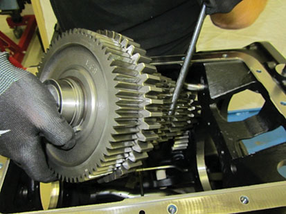
Using a J-hook, install the upper Counter Shaft into the Transmission Main Case.
Note: Place the back of the upper Counter Shaft into the rear Counter Shaft Bearing bore and carefully swing the Counter Shaft into place.
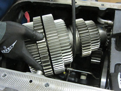
Place the Main Drive Gear on a bench and install the Input Shaft into the splines of the Main Drive Gear.
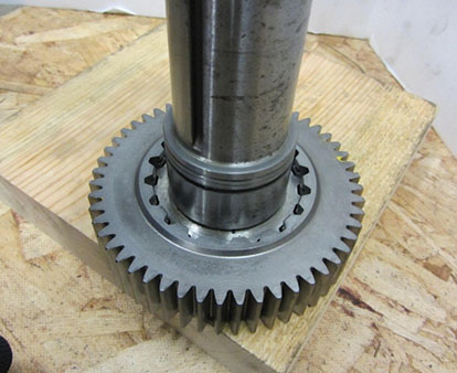
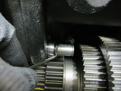
Install the snap ring that retains the Input Shaft to the Main Drive Gear. Place one corner of he snap ring in the Main Drive Gear groove. With a small screwdriver, slowly work around the Input Shaft until the snap ring is fully seated.
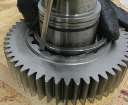
Install the Input Shaft and Main Drive Gear as an assembly into the Transmission Main Case.
Note: Counter Shaft Bearings must not be installed to complete the installation.
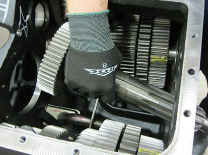
Install the Input Shaft Spacer on the Input Shaft.
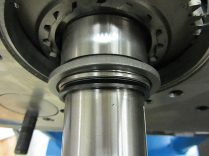
Place the Input Shaft Bearing over the Input Shaft. Using the Input Shaft Bearing Driver, press the bearing onto the Input Shaft and into the Transmission Main Case.
Note: Drive the bearing into the Transmission Main Case and wiggle the Input Shaft assembly back out. Continue driving the bearing onto the Input Shaft. Repeat this process until there is enough room to install the Input Shaft snap ring.
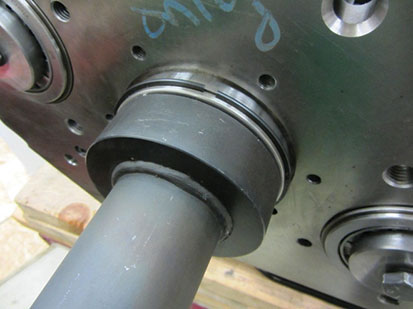
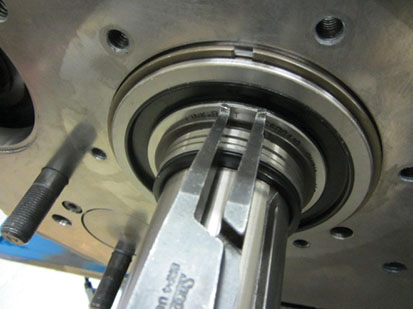
Install the Input Shaft snap ring.
Line up the marked tooth on the lower Counter Shaft with the two marked teeth on the Main Drive Gear.
Using the rear Counter Shaft Bearing Driver, drive the rear bearing onto the lower Counter Shaft and into the intermediate wall of the Transmission Main Case until there is enough room to install the rear Counter Shaft Bearing snap ring.
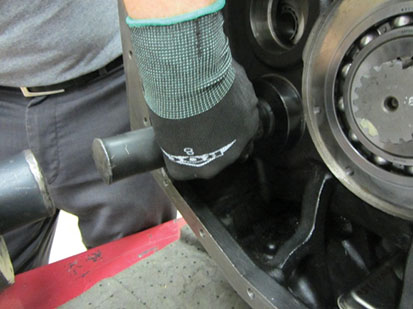
Install the rear lower Counter Shaft Bearing snap ring.
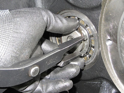
Install the front lower Counter Shaft Bearing onto the Counter Shaft and into the bore of the Transmission Main Case.
Note: Using an old race for the front Counter Shaft Bearings helps keep the rollers in place during installation.
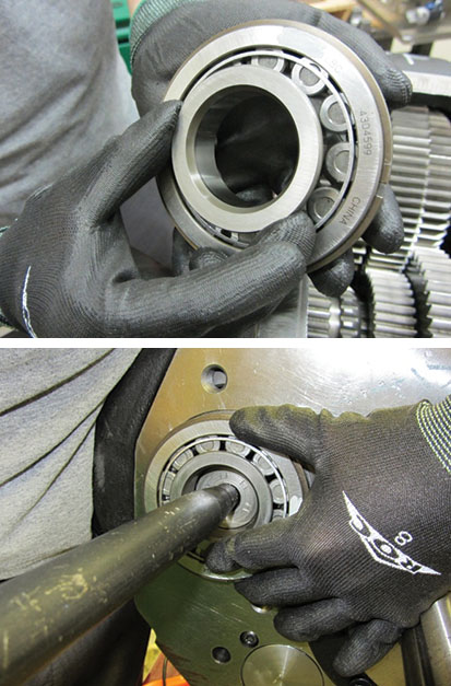
Install the front lower Counter Shaft Bearing retaining washer and bolt and torque to 90–120 lb-ft.
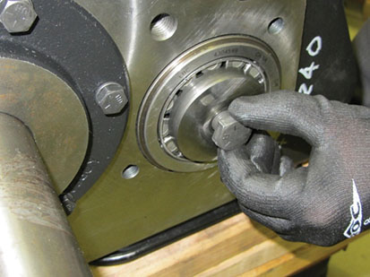
Place the upper Reverse Idler on top of the lower Counter Shaft; tuck it as close to the side of the case as possible.
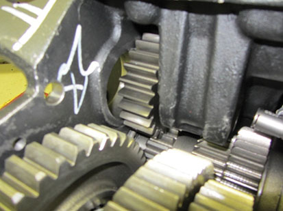
Using a J-hook, install the Main Shaft assembly into the Transmission Main Case by placing the rear of the Main Shaft through the opening in the intermediate wall and lowering the front of the Main Shaft into place. Pull the Main Shaft forward and pilot the tip into the Input Shaft Bushing.
Note: Reverse Gear needs to be tucked into 1st Gear (over the 1st–Reverse Sliding Clutch) during installation to ensure adequate room to position the Main Shaft.
Caution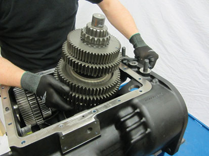
Install the rear Main Shaft Bearing partially into the case to aid in supporting the Main Shaft assembly.
Note: Ensure the Reverse Gear remains tucked against 1st Gear.
Line up the marked tooth on the upper Counter Shaft with the two marked teeth on the Main Drive Gear.
Note: Ensure the lower Counter Shaft is still in time with the Main Drive Gear before moving the upper Counter Shaft into place.
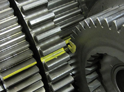
Using the rear Counter Shaft Bearing Driver, drive the rear bearing onto the upper Counter Shaft and into the intermediate wall of the Transmission Main Case until there is enough room to install the rear Counter Shaft Bearing snap ring.
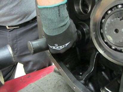
Install the rear upper Counter Shaft Bearing snap ring.
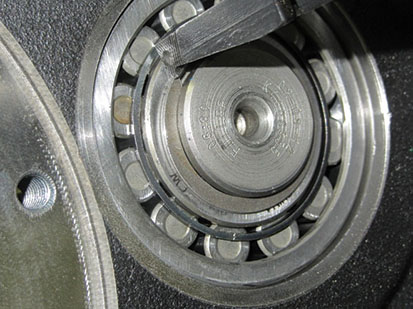
Install the front upper Counter Shaft Bearing onto the Counter Shaft and into the bore of the Transmission Main Case.
Note: Using an old race for the front Counter Shaft Bearings helps keep the rollers in place during installation.

Install the front lower Counter Shaft Bearing retaining washer and bolt and torque to 90–120 lb-ft.

Place the Eccentric Washer over the upper Reverse Idler Shaft. Pilot the shaft into the Reverse Idler Gear leaving room to slip the front thrust washer into place.
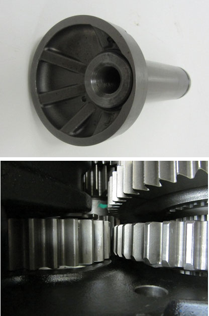
Thread a 5/8-18" x 2" bolt into the back of the upper Reverse Idler Shaft. Using a hand maul and soft bar, drive the Reverse Idler Shaft into the bore until there is enough room to install the spiral snap ring on the front of the shaft.
Note: The cap screw fastening the front Counter Shaft Bearing retainers to the Counter Shaft is the same size and thread pitch needed for the Reverse Idler bore.
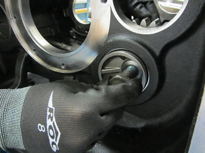
Install a new spiral lock retainer on the upper Reverse Idler Shaft.
Remove the rear Main Shaft Bearing and pull the Reverse Gear back into place in between the two Reverse Idlers. Ensure the Reverse Gear is pulled as far to the rear of the case as possible.
Note: Placing a hand maul in between the 1st and Reverse Gear will assist in keeping the Reverse Gear in position.
Install the keyed washer into the Reverse Gear.
Install the Reverse Gear snap ring, place one corner into the groove in the gear and, using two small screwdrivers, pry it into place working slowly around the Main Shaft unit the snap ring is fully seated.
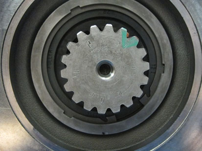
Install the rear Main Shaft Bearing onto the Main Shaft. Using a plastic hammer or hammer and brass drift, drive the bearing into the bore of the intermediate wall.
Note: The rear Main Shaft Bearing is splined and has a double open tooth area that goes over the key of the Main Shaft, similar to the Main Shaft Sliding Clutches.
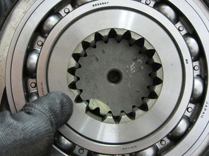
Install the rear Main Shaft Bearing retaining plate and cap screws; torque the six cap screws to 35–45 lb-ft.
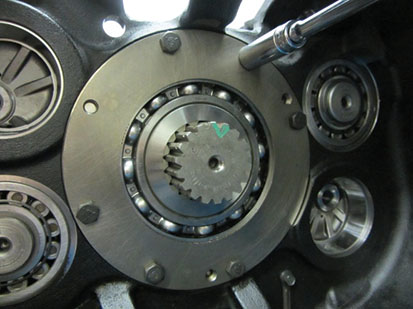
Install the Auxiliary Drive Gear onto the Transmission Main Case Main Shaft.
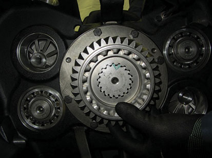
Install the Auxiliary Drive Gear snap ring.
Note: If the snap ring will not fit into the groove verify that the Main Shaft is pulled to the rear of the Transmission.
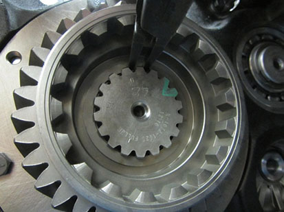
Install both upper and lower Auxiliary Counter Shaft Front Bearing Races into the Transmission Main Case intermediate wall.
Install the Reverse Idler Feed Tube and new metal clip.
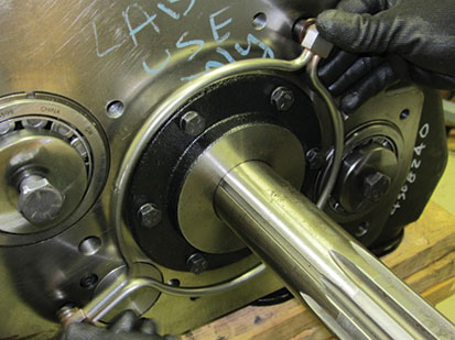
Install the oiling system halo through the bores in the front of the Transmission Main Case until all O-rings are fully seated.
Install the Front Bearing Cover and gasket.
Notice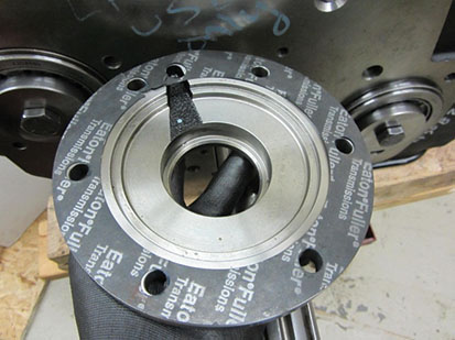
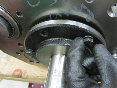
Install the six cap screws that fasten the Front Bearing Cover to the Transmission Main Case. Torque the cap screws to 35–45 lb-ft.
Auxiliary Section Installation
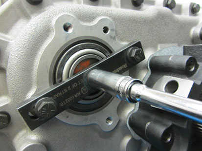
Ensure that the Auxiliary Counter Shaft Support Straps are still installed and all three cap screws are snug.
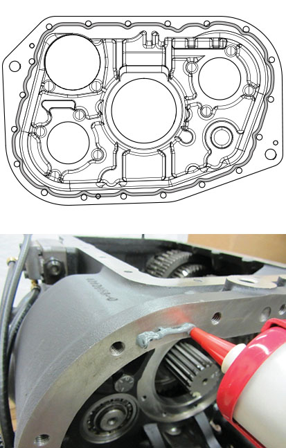
Apply Loctite 5810F RTV or anaerobic 5188 sealant to the Auxiliary Case to Main Case joint, using an 1/8" bead apply the sealant inward of all cap screws holes.
Note: Follow the pattern in the image below. Parts must be assembled within 30 minutes of applying sealant. The area must be clean of contaminants, ensure surfaces are adequately prepped.
Using an overhead crane, lift the Auxiliary Case assembly and line up the two holes in the Auxiliary Case with the Transmission Main Case alignment pins. Push the case forward toward the Transmission Main Case.
Note: Verify the Auxiliary Counter Shafts are still timed to the Auxiliary Reduction Gear before installing. This will allow for easier installation and timing to the Auxiliary Drive Gear.
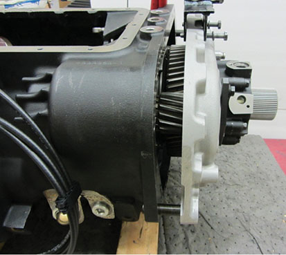
Once the Auxiliary Case is pushed as far into the Transmission Main Case as possible, remove the Auxiliary Section Lifting Bracket. Loosen the Auxiliary Counter Shaft Support Strap cap screws and fully seat the Auxiliary Case to the Transmission Main Case.
Note: Fully seating the Auxiliary Section to the Transmission Main Case should take light force; do not draw it in with bolts. If the Auxiliary Section will not come flush with the Transmission Main Case, a timing issue with the Auxiliary Section gearing may be the cause.
Install the 19 cap screws that fasten the Auxiliary Section to the Transmission Main Case. Torque bolts to 35–45 lb-ft.
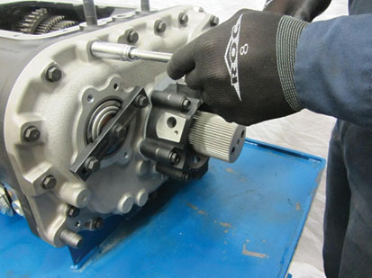
Install required shim into bearing bore, apply Loctite 5810F RTV or anaerobic 5188 sealant to the Counter Shaft Bearing Cover position on the Auxiliary Case and install cover. Torque cap screws to 30–35 lb-ft.
Note: Follow the pattern in the image below. Parts must be assembled within 30 minutes of applying sealant. The area must be clean of contaminants, ensure surfaces are adequately prepped.
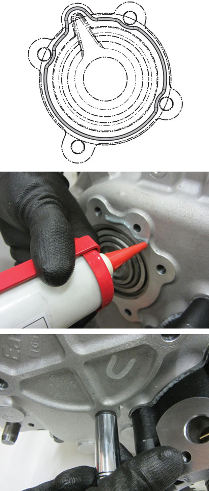
New Style Au
Verify that the O-ring groove is clean of debris.
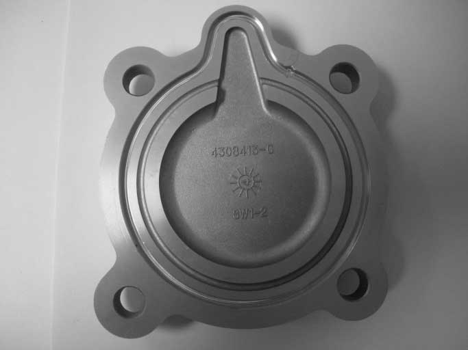
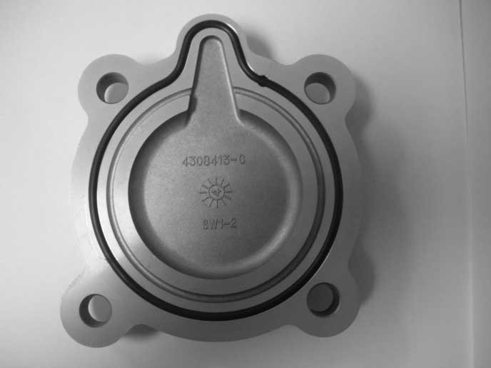
Start at the top by the oil passage and press the O-ring in the groove around the cover. Working it in evenly on each side until the O-ring is fully seated.
Note: A small amount of transmission oil may be used if needed to assist on the installation of the O-ring.
Install the countershaft cover on the Auxiliary Section. Torque cap screws 30-35 lb-ft.
