Output Shaft Speed Sensor
Special Instructions
The Directional Output Shaft Speed Sensor is used on the Fuller® Advantage model Transmissions. The Output Shaft Speed Sensor location may vary depending on OEM design specifications. The sensor will be located at 10 o’clock on the Output Shaft Housing in heavy-duty models
Special Tools
- Basic hand tools
Component Identification
 |
1. Cap Screw 2. 2-Way Directional Output Shaft Speed Sensor |
Output Shaft Speed Sensor Removal
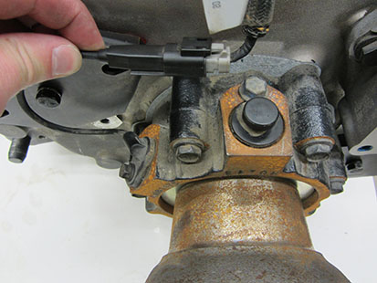
Disconnect the Transmission Harness from the Output Shaft Speed Sensor pigtail connector.

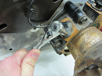
Remove the sensor retaining bolt.

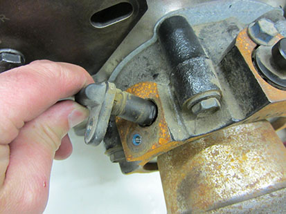
Remove the speed sensor from the Transmission Rear Bearing Cover.

Output Shaft Speed Sensor Installation
Using a smooth, twisting motion, fully insert the Output Shaft Speed Sensor in the Transmission Rear Bearing Cover opening.

Install the Retaining Bolt and tighten to 8–10 lb-ft (11–13 N•m).

Apply included material to the Sensor Connector terminals.
Note: Apply just enough material to cover the end of the terminal.
Note: Use only Eaton lubricant 5564527. (Nye Lubricants NYOGEL 760G - For MSDS safety or other information see www.nyelubricants.com)
Reconnect the Transmission Harness to the Output Shaft Speed Sensor and install the cable tie.
