Transmission Electronic Control Unit (TECU)
Special Instructions
None
Special Tools
Basic hand tools
Component Identification
 |
1. Nut 2. Bracket 3. Transmission Electronic Contril Unit (TECU) 4. 38-Way Connectors 5. Cap Screw (Located inside 38-way connectors) |
Transmission Electronic Control Unit (TECU) Removal
Connect ServiceRanger to vehicle and create a service activity report to save current configuration settings before removing the TECU from the Transmission. (Refer to “ServiceRanger User Guide” TCMT0072 for more information.)
CautionCautionDisconnect the following connectors:
- Using a 5/32” hex wrench, unscrew and disconnect the Transmission Harness 38-way Connector and Vehicle Interface 38-way Connector.
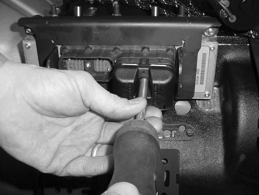
Using a 7/16” socket, remove the 3 mounting nuts.
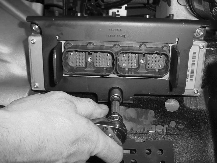
Remove the Transmission Controller Retaining Bracket.
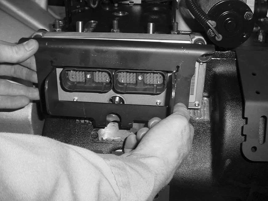
Remove the Transmission Controller assembly from the locating studs.
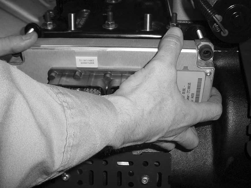
Transmission Electronic Control Unit (TECU) Installation
Position the Transmission Controller on the locating studs.

Place the Transmission Controller Retaining Bracket over the TECU.

Using a 7/16” socket, install the 3 Transmission Controller mounting nuts and tighten to 7–9 lb-ft (9.5–12.2 N•m).

Reconnect the following connectors:
Caution- Using a 5/32” wrench, reconnect the Transmission Harness 38-way Connector and tighten to 25 +/- 3 lb-in (2.82 +/- 0.33 N•m).
- Using a 5/32” wrench, reconnect the Vehicle Interface 38-way Connector and tighten to 25 +/- 3 lb-in (2.82 +/- 0.33 N•m).
- Reconnect the negative battery cable.

Connect ServiceRanger to vehicle and compare recorded configuration settings (step 1 in removal process) to the replacement TECU. Update and save all configurations that are different. (Refer to “ServiceRanger User Guide” TCMT0072 for more information.)
To operate properly, the system must be calibrated as follows:
Notice- Turn ignition switch on. Allow Transmission to power up.
- Turn ignition off. Wait 2 minutes.
ECA Calibration
Start the truck and let the system air up.
With ServiceRanger connected perform Clutch ECA Calibration in Service Routines Option.
Grade Sensor Calibration
Key on, engine off with truck on level ground.
With ServiceRanger connected perform Grade Sensor Calibration in Service Routines Option.
Grade Sensor Manual Calibration
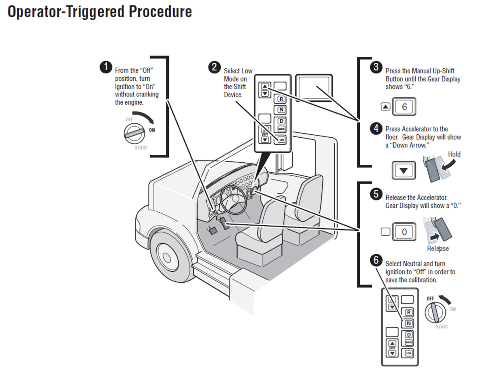
See Operator-Triggered Procedure below
