Electrical Pretest
Overview
The pretest does not relate to any specific fault code, but must be completed before performing Fault Code Isolation table procedures. The pretest verifies the batteries are fully charged.
All Generation 3 products require the OEM to supply power to the Electronic Control Unit (ECU) and to the optional Electric Clutch Actuator (ECA).
Detection
There is no detection process specifically for the basic electrical supply; however, failures of this type are generally detected by the transmission or driver as some other type of fault code or symptom.
Fallback
There is no fallback for the electrical pretest; however, it may affect other systems.
Possible Causes
The pretest can be used for:
- Low batteries
- Starter/Battery connections
- Main power harness to the Transmission Electronic Control Unit (TECU)
Additional Tools
- Basic hand tools
- Eaton Test Adapter Kit
- Digital Volt/Ohm meter
- Troubleshooting Guide
- Battery Load tester
- ServiceRanger a PC-based service tool
Component Identification
TECU Power Harness
OEM is responsible for overcurrent protection on this circuit.

| 1. 30 AMP Fuse |
| 2. TECU Connector (Vehicle Interface) |
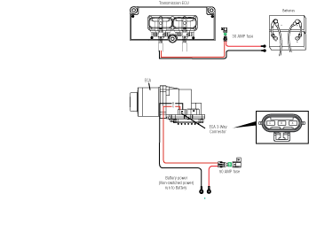
Heavy-Duty Electric Clutch Actuator (ECA) Power Harness
OEM is responsible for overcurrent protection on this circuit. ECA products are 12-volt only.

| 1. 50 AMP Fuse |
Heavy-Duty Electric Clutch Actuator (ECA) Power Harness
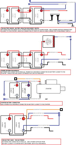
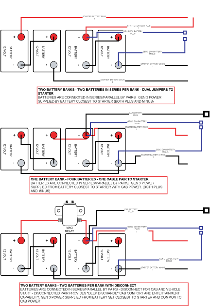
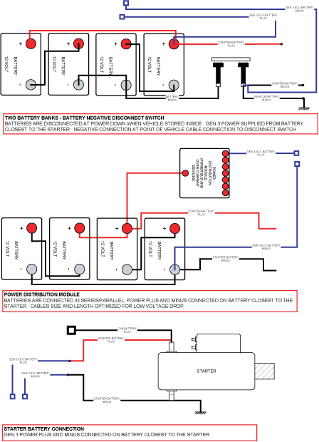
It is the OEM responsibility to provide power and ground to the TECU and ECA from the battery which supplies the starter.
The power (+) connection must include overload protection per Federal Motor Carrier Safety Regulations, Section 393.31. The TECU main power and ground must be a direct connection from the battery posts to the TECU connector.
At 120° C, these conductors must be able to carry 30 amps @ 9 volts with no more than 0.05 ohms per wire (0.1 ohms total) for a total voltage drop from the battery posts to the TECU connector not to exceed 3.0 volts. ECA main power and ground must be able to carry 50 amps @ 9 volts with no more than 0.025 ohms per wire (.05 ohms total) at 120° C. Duration of the 50 amp current draw will not exceed 20 milliseconds.
The main power 30-amp fuse connection for the TECU must be identified with a tag at the battery.
The main power 50-amp fuse connection for the ECA must be identified with a tag at the battery.
The battery positive post and negative post must be disconnected PRIOR to any type of welding on any Fuller Automated Transmission-equipped vehicles.
Removal of fuses is not recommended as the method of disconnecting power from the ECU. Making and breaking a circuit through tin plated terminals (e.g. ring terminals, fuses, most connectors) will destroy the plating on the terminal. Opening a switch contact or the main power link is the recommended method of interrupting power.
Application of more than 36 volts to the system (such as jump-starting) will cause system shutdown and possible electrical component damage.
Do not switch off the battery and ignition power and ground to the TECU during the engine start process.
Preferred +12 Volt Connections
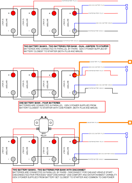
Preferred +12 Volt Connections
Preferred +24 Volt Connections
Preferred +24 Volt Connections
TECU Ignition Circuit
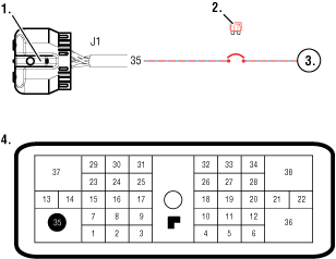
- TECU connector (vehicle interface)
- 10 AMP only, manual resetting circuit breaker OR 10 AMP fuse
- Ignition Key Switch
Note: Run to main power lead that feeds the ignition bus (OEM responsible for overcurrent protection on this line)
- TECU Connector (vehicle interface) front view
| From | To |
|---|---|
| J1-35 | VIGN |
Battery and ignition power and ground to the TECU must not be switched off during the engine start process.
J1939 Data Link
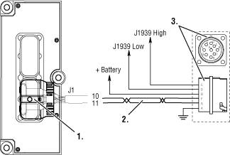
- TECU connector (vehicle interface)
- J1587 Data Link
- 9-Way, for transmission diagnostics
J1939 Troubleshooting
- Check the resistance of the J1939 Data Link.
- Key off. Measure resistance between the 9-way diagnostic connector Pin C and Pin D and record the reading. The reading should be 60 ohms of resistance (between 50 and 70.)
- Check resistance between Pin C and Pin A and the resistance between Pin D and Pin A. These two readings should be 10K ohms or greater (open circuit).
Note: Pin C = J1939+, Pin D = J1939-, Pin A is a chassis ground
- If an Inactive data link fault code is being reported by the TECU, See "Product Diagnostic (PD) Mode" PDM should be utilized before any further steps are taken.
Electrical Pretest
Key off.
Remove and clean all battery and battery-to-frame connections.
Remove and clean ground supply to engine ECU.
Inspect starter/battery and inline 30 amp fuse holder connections for corrosion or damaged contacts. Also, inspect the 50 amp fuse holder on vehicles equipped with an Electronic Clutch Actuator (ECA).
Measure voltage across batteries.
If voltage is 11 to 13 volts on a 12- volt system or 22 to 26 on a 24 volt system, refer to OEM guidelines for battery load test. Repair or replace batteries as required. Go to Step B
If voltage is outside of range, repair or replace batteries and charging system as required. Repeat this step.
Locate diagnostic port on Transmission Harness.
Key on.
Measure voltage between Pin C and the battery negative post.

If voltage is 0.70 volts or less, Go to Step C
If voltage is outside of range, repair battery ground supply to Transmission Electrical Control Unit (TECU). Repeat test.
Locate diagnostic port on Transmission Harness.
Key on.
Measure voltage between Pin B and Pin C.

If voltage is within 0.6 volts of battery voltage, Go to Step D
If voltage is outside of range, Repair battery power supply to TECU. Fuse may be blown. Repeat test.
Key on.
WarningMeasure voltage between Pin A and Pin C.

If voltage is within 0.6 volts of battery voltage, For non-ECA products, test complete. See "Diagnostic Procedures"Go to Step E
If voltage is outside of range, repair ignition power supply to TECU. Fuse may be blown. Repeat test.
Key off.
Disconnect battery negative.
Disconnect ECA 3-way connector.
Reconnect battery negative.
Measure voltage between Pin B and Pin C of 3-way connector.
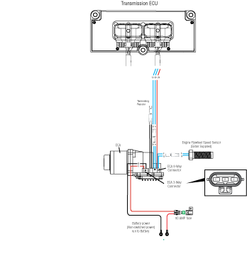
If voltage is within 0.6 volts of battery voltage, test complete. See "Diagnostic Procedures"
If voltage is outside of range, repair battery power supply to ECA. Fuse may be blown. Repeat test.