Start Enable Relay Contact Test
Overview
This symptom-driven test is performed if the engine does not crank with the Shift Lever in neutral, and there are no Active or Inactive codes.
Detection
The Transmission Electronic Control Unit (TECU) has no fault detection capability for this failure. The failure is observed by the driver when operating the vehicle. To observe this failure, attempt to start the vehicle.
Fallback
This symptom has no affect on vehicle operation; however, if the failure occurred before the engine was started, it is possible the engine will not start.
Possible Causes
This symptom can be caused by any of the following:
- Start Enable Relay
- Starter Solenoid wiring
- Vehicle Harness
Component Identification
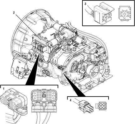 |
1. 38-Way Transmission Harness Connector 2. Transmission Electronic Control Unit (TECU) 3. 5-Way Start Enable Relay Socket 4. 4-Way Diagnostic Connector |
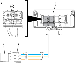 |
1. Transmission Electronic Control Unit (TECU) 2. 38-Way Vehicle Harness Connector 3. 5-Way Start Enable Relay Socket 4. 5-Way Start Enable Relay |
 |
Start Enable Relay Circuit States (Normally Open) 5. Open Relay - Key Off (Non-energized State) 6. Closed Relay - Key On and Transmission Confirmed in Neutral (Energized State) |
 |
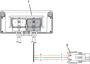 |
1. Transmission Electronic Control Unit (TECU) 2. 4-Way Diagnostic Connector |
 |
Start Enable Relay Contact Test
Key off.
Inspect starter/battery and in-line fuse holder connections for integrity.
Measure voltage across batteries.

If voltage is 11–13 volts on a 12-volt system or 22 to 26 on a 24 volt system, proceed with battery load test. Repair or replace batteries as required and Go to Step B
If voltage is outside of range, repair or replace batteries and charging system as required. Repeat test.
Locate diagnostic port on Transmission Harness.
Key on.
Measure voltage between Pin C and the battery negative post.
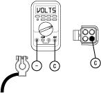
If voltage is 0.70 volts or less, Go to Step C
If voltage is outside of range, repair battery ground supply to TECU. Repeat test.
Locate diagnostic port on Transmission Harness.
Key on.
Measure voltage between Pin B and Pin C.
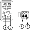
If voltage is within 0.6 volts of battery voltage, Go to Step D
If voltage is outside of range, repair battery power supply to TECU. Fuse may be blown. Repeat test.
Key on.
Measure voltage between Pin A and Pin C.

If voltage is within 0.6 volts of battery voltage, Go to Step E
If voltage is outside of range, repair ignition power supply to TECU. Fuse may be blown. Repeat test.
Key off.
Disconnect negative battery cable.
Disconnect Vehicle Harness 38-way connector.
Reconnect negative battery cable.
Key on.
Engage starter.
Note: The Start Enable Relay must be wired according to Eaton GEN III requirements (shown on previous page) for this test to work properly. If wired differently, consult OEM for correct wiring schematic.
If engine cranks, Go to Step F
If engine does not crank, Go to Step G
Key off.
Remove the Start Enable Relay.
Key on.
Engage starter.
If vehicle cranks, repair short to power on Vehicle Harness. Go to Step V
If vehicle does not crank, replace Start Enable Relay. Go to Step V
Key on.
Disconnect negative battery cable.
Reconnect Vehicle Harness 38-way connector.
Reconnect negative battery cable.
Place a jumper wire across connector contact 30 and contact 87.
WarningKey on. Verify neutral on Gear Display.
Engage starter.

If engine cranks, replace the Start Enable Relay. Go to Step H
If engine does not crank, refer to OEM for repair of Vehicle Harness or starter.
Key off.
Disconnect negative battery cable.
Disconnect Vehicle Harness 38-way connector.
Disconnect the Start Enable Relay.
Measure resistance between Pin 87 of the Start Enable Relay connector and Pin 26 of the Vehicle Harness 38-Way connector.
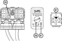
If resistance is 0 to 0.3 ohms, Go to Step V
If resistance is greater than 10K ohm, repair wiring and Go to Step V
Key off.
Reconnect all connectors.
Key on.
Start the engine to determine whether the Start Enable Relay contact complaint has been repaired.
If engine starts, test complete.
If engine does not start Go to Step A to error in testing.