Fault Code 26: Clutch Slip
J1587: MID 130 SID 55 FMI 10
J1939: SA 3 SPN 522 FMI 10
Overview
The UltraShift PLUS Transmission is equipped with a Heavy Duty Electronic Clutch Actuator (ECA) Clutch. The Transmission Electronic Control Unit (TECU) monitors engine speed and Input Shaft Speed Sensor values to calculate clutch slip. Fault Code 26 indicates that a clutch slip event has occurred.
Detection
The TECU calculates a significant variance between the engine speed and Input Shaft Speed Sensor values.
Conditions to Set Fault Code Active
FMI 10 – Abnormal Rate of Change: The TECU monitors and compares both Input Shaft Speed and engine speed. If the TECU calculates that engine speed is greater than Input Shaft Speed by over 150 RPM and remains at 50 RPM or higher for 1.3 seconds.
Fallback
FMI 10
- “F” flashes in gear display.
- Service light flashes (if equipped).
- During a slip event the engine torque will be decreased.
Conditions to Set Fault Code Inactive
FMI 10: Ignition key is turned off and TECU is powered down.
Possible Causes
FMI 10
- Clutch
- Excessive release bearing greasing
- Contamination from oil leaks
- Wear or damage
- Damage due to excessive abuse
- Clutch adjustment mechanism not functioning properly.
- Clutch worn out
- OEM Engine
- Intermittent loss of engine speed over the J1939 data link
- Engine oil contamination on clutch facings
- Transfer Dump - Application
Additional Tools
- ServiceRanger4
- Solo Clutch Cam Reset Tool - RR1005CL
Component Identification
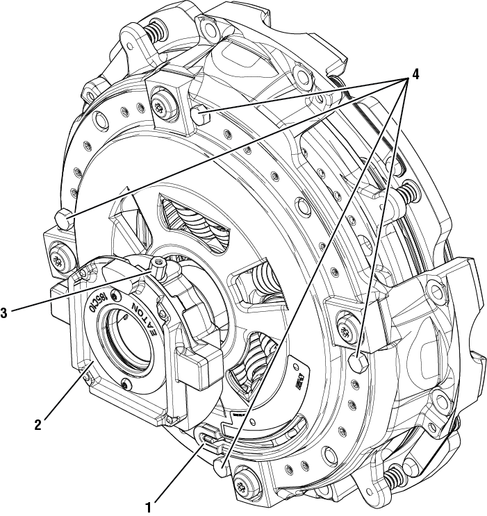 |
Eaton ECA Clutch 1. Clutch Wear Tab 2. Release Bearing 3. Release Bearing Grease Zerk 4. Shipping Bolts (qty 4) |
Fault Code 26 Troubleshooting
Record the transmission fault codes, FMIs, occurrences, and timestamps from the Service Activity Report created during the Diagnostic Procedure.
Set parking brake and chock wheels.
Key on with engine running. Run engine for 2 minutes.
Connect ServiceRanger.
Retrieve and record the transmission fault codes and FMIs and their occurrences and timestamps.
Retrieve and record fault codes from the engine, ABS, and other vehicle systems using the OEM-specific diagnostic scan tool.
Notice
If non-transmission fault codes related to the J1939 Data Link are present, troubleshoot per OEM guidelines.
If transmission Fault Code 35, Fault Code 36 or Fault Code 64 are present, troubleshoot per Fault Code Isolation Procedure Index.
If Fault Code 26 is Active or Inactive, Go to Step B
Key off.
NoticeRemove single bolt for clutch housing access cover.
Locate and record clutch part number.
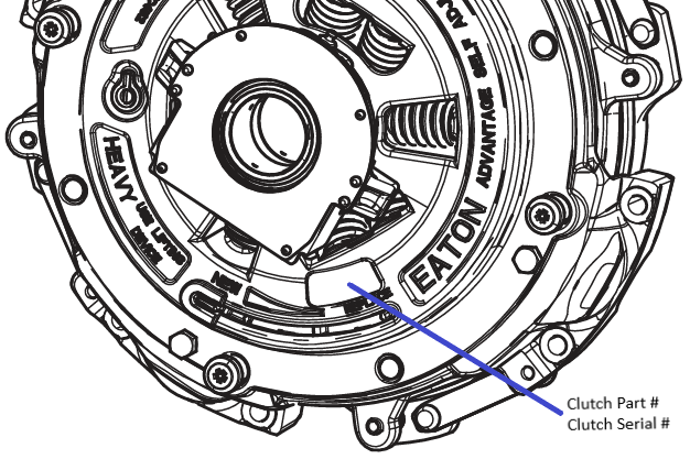
Note: May need to rotate engine to view clutch part number.
Close and secure the clutch housing access cover and torque to 21-27 lb-in [2.4-3.1 Nm].
Refer to OEM and/or Engine Manufacturer and record engine torque rating.
Compare clutch part number torque rating and engine torque rating.
If clutch part number torque rating is equal to or greater than engine torque rating, Go to Step C
If clutch part number torque rating is less than engine torque rating, install the correct clutch part number based on engine specifications. Go to Step V
| Clutch Part Number | Clutch Torque Rating |
|---|---|
| 122002-35A | 1850 lb-ft |
| 122002-35EX | 1850 lb-ft |
| 122003-42A | 2250 lb-ft |
Key off.
NoticeKey on with engine off.
Connect ServiceRanger.
Go to Configuration.
Record “Transmission Model Number” Current Value.
Locate transmission part information tag on transmission and record transmission model number.
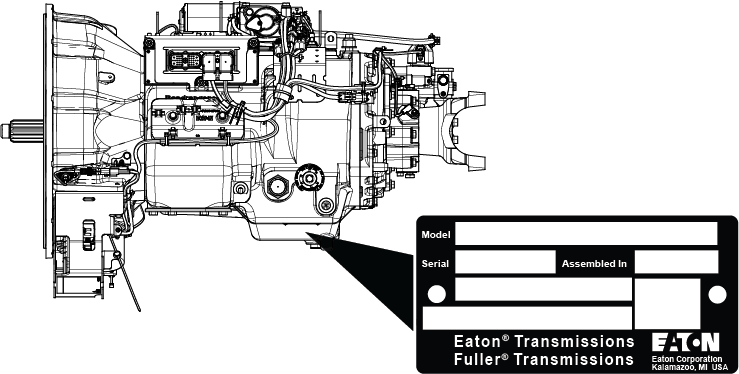
Compare transmission model number in ServiceRanger and on part information tag.
If transmission model numbers are the same, Go to Step D
If transmission model numbers are not the same, retrieve Snapshot and VPA data by creating a Service Activity Report within ServiceRanger. Select “Send To Eaton”. Contact Eaton at (800) 826-4357 for further diagnostic instructions. Go to Step V
Key off.
NoticeKey on with engine off.
Connect ServiceRanger.
Go to Data Monitor.
From the Default Parameter Files, select “J1939 Clutch Actuator”.
In ServiceRanger, monitor 520214 - Clutch Inertia Brake TP Delta and record value in table.
If reading is greater than 27°, Go to Step E
If reading is less than 27°, clutch is at the normal operating position. Go to Step V
Note: If vehicle is used in a Transfer Dump - Application and Snapshot data indicates 0 (zero) engine RPM when the fault code sets Active, this is considered a characteristic. Retrieve Snapshot and VPA data by creating a Service Activity Report within ServiceRanger. Select “Send To Eaton”. Contact Eaton at (800)826-4357 for further diagnostic instructions.
| Parameter | Range | Reading(s) |
|---|---|---|
| Clutch Inertia TP Delta | 16-27° |
Key off.
NoticeRemove single bolt for clutch housing access cover.
Inspect inside clutch housing for signs of oil or grease contamination.
NoticeInspect for broken clutch or spring material and other signs of a clutch failure.
NoticeDocument any damage or failures with pictures.
If release bearing grease contamination is found due to recent greasing of the release bearing, road test vehicle to remove grease build up. Go to Step V
If one or more shipping bolts are installed, refer to CLSM0200 Clutch Service Manual and remove shipping bolts. Go to Step V
If engine oil contamination is found, refer to OEM guidelines regarding repair or replacement. Go to Step V
If physical signs of a clutch failure are present, replace the Heavy-Duty ECA Clutch. Go to Step V
If no issues are found in the clutch housing, Go to Step F
Key off.
Check the position of the Wear Tab located on the clutch cover assembly.
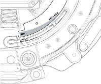
If Wear Tab is in the “Replace” position, replace Heavy Duty ECA Clutch. Go to Step V
If Wear Tab is not in the “Replace” position, Go to Step G
Key on.
Connect ServiceRanger.
Go to “Service Routines”.
Select “Start” Open Clutch and follow on-screen prompts.
Caution
Key off.
Insert the Solo Clutch Reset Tool (RR1005CL) through the clutch housing access opening under the release bearing with the threaded bolt in the clutch cam slot.
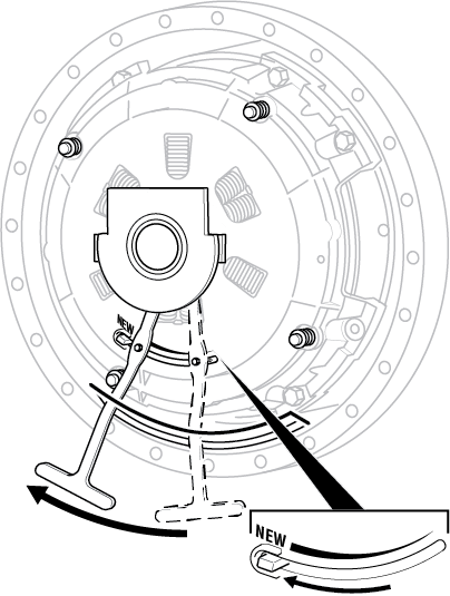
Slide the tool and clutch cam to the New position.
Slide the tool and clutch cam toward the Replace position.
Slide the tool and clutch cam to the New position and hold in the New position.
Note: If the clutch cam does not move, the cam is seized due to contamination. Repeat Steps 1 through 5 in an attempt to free the clutch cam.
While holding the tool and clutch cam in the New position, keep hands out of the clutch housing and request an assistant to Key On with the Engine Off, to close the clutch. Do not crank or start engine.
CautionRemove tool from clutch housing.
Note: An assistant is required to perform this step.
If clutch cam is seized, Heavy Duty ECA Clutch replacement is required. Go to Step V
If clutch cam is in the New position, Go to Step I
Key on.
Connect ServiceRanger.
Go to “Service Routines”.
Select “Start” Adjust Clutch and follow on-screen prompts.
CautionClose and secure the clutch housing access cover and torque to 21-27 lb-in [2.4-3.1 Nm].
Key off.
Reconnect all connectors and verify that all components are properly installed.
Key on with engine off.
Clear fault codes using ServiceRanger.
Drive vehicle and attempt to reset the code or duplicate the previous complaint.
Check for fault codes using ServiceRanger.
If no codes set and vehicle operates properly, test complete.
If Fault Code 26 sets Active during the test drive, refer to Contact Information and contact Eaton for further diagnostics.
If a fault code other than 26 sets, troubleshoot per Fault Code Isolation Procedure Index.