Transmission Not Engaging a Gear From Neutral
Overview
This symptom-driven test is performed if the transmission does not engage a gear from neutral and there are no Active or Inactive fault codes.
Detection
Transmission not engaging a gear from Neutral.
Possible Causes
- Vehicle Power and Ground
- Poor power or ground supply to TECU
- Bent, spread, corroded or loose terminals
- OEM Batteries
- Internal Failure
- Input Shaft Speed Sensor
- Internal Failure
- Parking Brake Switch
- Internal Failure
- Clutch
- Excessive abuse or damage
- Improper removal or installation
- Over-adjustment
- Electronic Clutch Actuator (ECA)
- Internal Failure
Component Identification
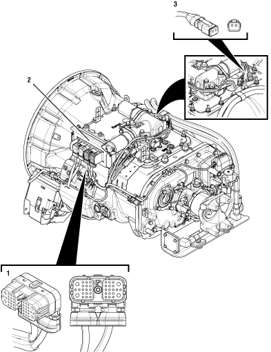 |
1. 38-Way Transmission Harness Connector 2. Transmission Electronic Control Unit (TECU) 3. Input Shaft Speed Sensor |
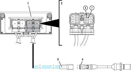 |
1. Transmission Electronic Control Unit (TECU) 2. 38-Way Transmission Harness Connector 3. Input Shaft Speed Sensor Connector 4. Input Shaft Speed Sensor |
 |
Transmission Not Engaging a Gear From Neutral Test
Perform the Electrical Pretest. Reference the Electronic Clutch Actuator (ECA) Identification Overview. Record the reading(s) from the Load Test in Step C of the Electrical Pretest in the table.
If Electrical Pretest fails, repair per Electrical Pretest instructions. Retest vehicle operation.
If Electrical Pretest passes, Go to Step B
| Battery | Voltage Drop | Load Test Status (Pass/Fail) |
|---|---|---|
| 1 | ||
| 2 | ||
| 3 | ||
| 4 | ||
| 5 |
Set parking brake and chock wheels.
Key on with engine running.
Verify shift device is in Neutral (N) position.
Verify Gear Display indicates Neutral (N).
Depress and hold service brake. Use the shift device to select Drive (D).
Monitor gear engagement and Gear Display reading.
If transmission goes into gear and the vehicle moves, Go to Step C
If transmission does not go into gear, Go to Step D
Drive vehicle and attempt to duplicate the previous complaint.
Return the transmission to Neutral and engage a gear from Neutral several times during the test drive.
If a fault code sets Active, troubleshoot per Fault Code Isolation Procedure Index.
If no fault codes set Active, but the complaint can be duplicated, take note of the Gear Display reading, Go to Step D
If no fault codes set Active and the complaint cannot be duplicated, test complete. If the complaint persists, refer to Contact Information and contact Eaton for further diagnostics.
Observe gear display when the transmission does not engage a gear from Neutral.
If gear display shows a solid “N”, Go to Step E

If gear display shows an “F”, check for fault codes using ServiceRanger and troubleshoot per Fault Code Isolation Procedure Index.

If gear display is blank, troubleshoot per the Power-Up Sequence Test. Reference the Electronic Clutch Actuator (ECA) Identification Overview.

If gear display shows a “- -” (double dash) or “* *” (double star), troubleshoot per the Power-Up Sequence Test. Reference the Electronic Clutch Actuator (ECA) Identification Overview.

If gear display shows a solid number or “-” (single dash), troubleshoot per the Main Case Control Test Main Case Control.

If gear display shows a blinking number, Go to Step N

The transmission requires the following conditions to be met in order to engage a gear from Neutral:
- The vehicle must be stopped, or must be moving at speeds lower than 2 miles per hour.
- The throttle must not be depressed.
- The brake pedal must be depressed before selecting a gear.
Verify that these operator influenced conditions are being met and attempt to engage a gear from Neutral.
If transmission engages a gear, Go to Step C
If transmission still does not engage a gear, Go to Step F
Key on with engine off.
Connect ServiceRanger.
In ServiceRanger, go to Data Monitor.
Select the “Engine and Brake” default parameter file.
Monitor Parameter 597 “Brake Switch”.
Depress Service Brake and verify that Brake Switch status changes to “Depressed”.
Release Service Brake and verify that Brake Switch status changes to “Released”.
Note: ServiceRanger covers Brake Switch status input from several possible sources. If the vehicle uses a Brake Switch source other than those programmed in ServiceRanger, the use of an OEM diagnostic tool may be required to see Brake Switch status.
If parameter matches Service Brake position, Go to Step G
If parameter does not match Service Brake position, repair Brake Switch input to the Transmission Electronic Control Unit (TECU) per OEM guidelines. Go to Step V
In ServiceRanger “Data Monitor,” clear selected parameters.
Select the “J1939 Transmission Speeds” default parameter file.
Monitor Parameter 161 “Input Shaft Speed”.
Start engine and monitor “Input Shaft Speed” with engine idling.
Record Input Shaft Speed reading in table.
NoticeCompare reading(s) in table.
If readings are out of range, Go to Step H
If readings are in range, no problem identified, test complete. If the complaint persists, refer to Contact Information and contact Eaton for further diagnostics.
| Sensor | Range | Reading |
|---|---|---|
| Input Shaft Speed | Within 25 RPM of Engine Idle Speed |
Key off.
NoticeDisconnect 38-Way Transmission Harness Connector from the TECU.
Verify no issues with 38-Way connector body for damage and bent, spread, corroded or loose terminals.
Measure resistance between 38-Way Transmission Harness Pin 7 and Pin 8. Record reading(s) in table.
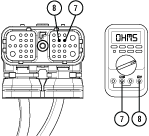
Compare reading(s) in table.
If readings are in range, Go to Step I
If readings are out of range, Go to Step M
| Pins | Range | Reading |
|---|---|---|
| 7 to 8 | 2.0k–4.5k ohms |
Measure resistance between 38-Way Transmission Pin 7 and ground. Record reading(s) in table.
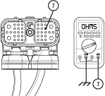
Compare reading(s) in table.
If readings are in range, Go to Step J
If readings are out of range, Go to Step L
| Pins | Range | Reading |
|---|---|---|
| 7 to Ground | Open Circuit (OL) |
Disconnect the 2-Way Transmission Harness Connector from the Input Shaft Speed Sensor.
Inspect 2-Way Connector body for damage and bent, spread, corroded or loose terminals.
Remove the Input Shaft Speed Sensor from the transmission.
Check the sensor body for any cracks or visual damage.
If damage is found, replace the Input Shaft Speed Sensor. Inspect the transmission for any internal damage and repair if required. Go to Step V
If no damage is found, Go to Step K
Key off.
Drain and save the transmission oil. Inspect oil for significant metal fragments.
Remove 8-bolt PTO cover.
Inspect main case gears for damage or excessive movement.
Inspect Shift Yokes and Sliding Clutches for damage or excessive wear.
If damage is found, repair or replace transmission as necessary. Go to Step V
If no damage is present and Input Shaft Speed Sensor is secure and properly seated, replace Transmission Harness and Input Shaft Speed Sensor. Go to Step V
Note: If unsure whether damage or wear is significant, take pictures of the transmission gearing. Ensure these pictures are clear and the components are easily visible. Email these pictures to auto.rtw@eaton.com and contact Eaton at (800) 826-4357.
Key off.
Disconnect the 2-Way Input Shaft Speed Sensor Harness Connector.
Inspect 2-Way Connector body for damage and bent, spread, corroded or loose terminals.
Check the sensor body for any cracks or visual damage.
Measure resistance between 2-Way Input Shaft Speed Sensor Connector Pin 2 and Pin 1. Record reading(s) in table.
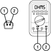
Measure resistance between 2-Way Input Shaft Speed Sensor Connector Pin 2 and ground. Record reading(s) in table.

Compare reading(s) in table.
If readings are out of range, replace Input Shaft Speed Sensor. Inspect the transmission for any internal damage and repair if required. Go to Step V
If readings are in range, replace Transmission Harness. Go to Step V
| Pins | Range | Reading(s) |
|---|---|---|
| 2 to 1 | 2.0k–4.5k ohms | |
| 2 to Ground | Open Circuit (OL) |
Key off.
Disconnect the 2-Way Input Shaft Speed Sensor Harness Connector.
Inspect 2-Way Connector body for damage and bent, spread, corroded or loose terminals.
Check the sensor body for any cracks or visual damage.
Measure resistance between 2-Way Input Shaft Speed Sensor Connector Pin 2 and Pin 1. Record reading(s) in table.

Compare reading(s) in table.
If readings are out of range, replace Input Shaft Speed Sensor. Inspect the transmission for any internal damage and repair if required. Go to Step V
If readings are in range, replace Transmission Harness. Go to Step V
| Pins | Range | Reading(s) |
|---|---|---|
| 2 to 1 | 2.0k–4.5k ohms |
In ServiceRanger go to “Data Monitor,” and clear selected parameters.
Select the “J1939 Transmission Speeds” default parameter file.
Monitor Parameter 161 “Input Shaft Speed”.
Start engine and monitor “Input Shaft Speed” with engine idling.
Depress and hold the service brake.
Place the Driver Interface Device in Drive (D).
Measure Input Shaft Speed while attempting to put the transmission into Drive. Record Reading(s) in table.
Compare reading(s) in table.
If readings are in range, troubleshoot per Main Case Control Test Main Case Control.
If readings are out of range, Go to Step O
| Sensor | Range | Reading(s) |
|---|---|---|
| Input Shaft Speed (while engaging a gear) | Less than 150 RPM |
Key on with engine running.
Set parking brake and chock wheels.
Connect ServiceRanger.
In ServiceRanger, go to “Service Routines”.
Run “Low Capacity Inertia Brake Test”.
If test passes, Go to Step P
If test fails, replace LCIB. Go to Step V
Key off.
Remove single retaining bolt securing Clutch Housing cover.
Through the Clutch Housing cover opening, inspect LCIB for grease contamination or blue heat discoloration.
Inspect inside Clutch Housing for signs of LCIB friction material or other signs of LCIB failure.
Inspect clutch for any sign of a failure including excessive clutch dust, broken springs, corrosion, or any condition that may contribute to the driver’s complaint.
Note: Reference Heavy-Duty Clutch Service Manual (CLSM0200) for full LCIB and Clutch inspection procedures.
If signs of a Clutch failure are found, replace ECA Clutch and LCIB. Go to Step V
If signs of an LCIB failure are found, replace LCIB. Go to Step V
If no issues are found, use ServiceRanger to collect the Snapshot and VPA files and refer to Contact Information and contact Eaton for further diagnostics.
Key off.
Reconnect all connectors and verify that all components are properly installed.
Key on with engine off.
Clear fault codes using ServiceRanger.
Drive vehicle and attempt to reset the code or duplicate the previous complaint.
Check for fault codes using ServiceRanger.
If no fault codes set Active and vehicle operates properly, test complete.
If a fault code sets Active during the test drive, troubleshoot per Fault Code Isolation Procedure Index.
If no fault codes set Active and the vehicle complaint is duplicated, refer to Contact Information and contact Eaton for further diagnostics.