Power-Up Sequence
Overview
This symptom-driven test is performed if the transmission system fails to fully power up at ignition on.
Detection
- Gear Display may be blank.
- Gear Display may show double dashes “- -”.
- Gear Display may show double stars “* *”.
- Engine may not crank.
- Transmission will not engage a gear from neutral.
Possible Causes
- Vehicle Power Supply Wiring
- Poor power or ground supply to TECU
- Bent, spread, corroded or loose terminals
- Wires grounded, open or shorted
- Vehicle Batteries
- Internal failure
- TECU
- Internal Failure
Component Identification
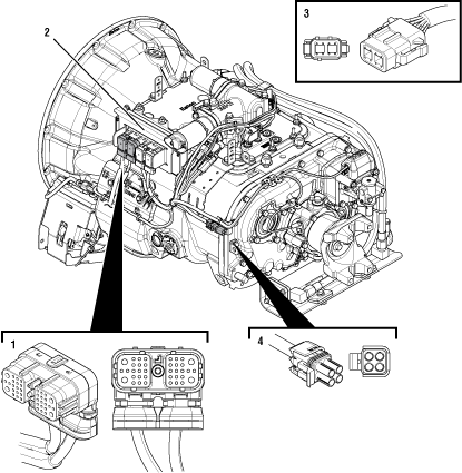 |
1. 38-Way Vehicle Harness Connector 2. Transmission Electronic Control Unit (TECU) |
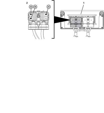 |
1. Transmission Electronic Control Unit (TECU) 2. 38-Way Vehicle Harness Connector |
Power-Up Sequence
Key off.
Measure voltage across all batteries. Record reading(s) in table.
Inspect starter, battery terminals and transmission 30-amp In-line Fuse Holder Connections for corrosion, loose terminals and bent or spread pins.
Visually inspect Vehicle Harness between the power supply and the TECU for signs of rubbing or chafing to the wiring.
Note: Some chassis use a power and ground distribution block separate from the battery or may route power and ground to the starter. Be sure to clean and inspect connections at this location and at the battery.
Verify that the battery voltage meets specifications for battery voltage.
If damage is found, repair or replace wiring per OEM guidelines. Go to Step V
If no damage is found and the battery voltage is out of range, refer to OEM guidelines for repair or replacement of batteries. Go to Step V
If no damage is found and the battery voltage is in range, Go to Step B
| Battery Voltage |
|---|
Key off.
Disconnect 38-Way Vehicle Harness Connector from TECU.
Inspect connector body for corrosion, damage and loose, spread or bent terminals.
Measure voltage between 38-Way Connector Pin 38 (Battery Positive) and Pin 36 (Battery Negative). Record reading(s) in table.
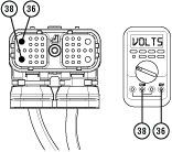
Compare reading(s) in table.
If readings are in range, Go to Step C
If readings are out of range, refer to OEM guidelines for repair or replacement of power and ground wring between the batteries and 38-Way Vehicle Harness Connector at the TECU. Go to Step V
| Pins | Range | Reading(s) |
|---|---|---|
| 38 to 36 | Within 0.6 V of Battery Voltage |
Key off.
Disconnect 38-Way Vehicle Harness Connector from TECU.
Inspect Connector body for damage and bent, spread, corroded or loose terminals.
Key on with engine off.
Measure voltage between 38-Way Connector Pin 35 (Ignition Positive) and Pin 36 (Battery Negative). Record reading(s) in table.
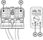
Compare reading(s) in table.
If readings are in range, Go to Step D
If readings are out of range, refer to OEM guidelines for repair of ignition voltage supply to TECU. Go to Step V
| Pins | Range | Reading(s) |
|---|---|---|
| 35 to 36 | Within 1.2 V of Battery Voltage |
Key off.
Verify TECU battery power and ground supply from the Vehicle Harness is connected properly and not corroded, damaged or loose.
Disconnect 38-Way Vehicle Harness Connector from TECU.
Inspect 38-Way Connector body for damage and bent, spread, corroded or loose terminals.
Load test the Vehicle Power Supply Harness with an external load source. Use a sealed beam headlamp or blower motor attached to Pin 38 (power) and Pin 36 (ground). Load Test for 5 minutes to verify the harness will carry a load with the 30-amp fuse installed.
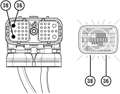
Wiggle the harness during the Load Test from vehicle batteries to TECU.
If issues are found with the power supply or connectors, refer to OEM guidelines for repair or replacement of OEM wiring. Go to Step V.
If the power supply does not carry a load, refer to OEM guidelines for repair or replacement of OEM wiring. Go to Step V
If no issues are found with the power supply or connectors and the power supply carries a load, Go to Step E
Key off.
Verify TECU ignition supply from the Vehicle Harness is connected properly and not corroded, damaged or loose.Disconnect 38-Way Vehicle Harness Connector from TECU.
Inspect 38-Way Connector body for damage and bent, spread, corroded or loose terminals.
Key on with engine off.
Load test the Vehicle Ignition Supply Harness with an external load source. Use a sealed beam headlamp or blower motor attached to Pin 35 (ignition) and Pin 36 (ground). Load Test for 5 minutes to verify the harness will carry a load with the 10-amp fuse installed.
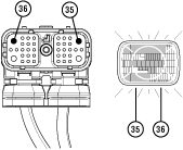
Wiggle the harness during the Load Test from vehicle ignition to TECU.
If issues are found with the ignition supply or connectors, refer to OEM guidelines for repair or replacement of OEM wiring. Go to Step V
If the ignition supply does not carry a load, refer to OEM guidelines for repair or replacement of OEM wiring. Go to Step V
If no issues are found with the ignition supply or connectors and the ignition supply carries a load, Go to Step F
Key off.
Refer to the OEM and identify the TECU location on the vehicle J1939 Data Link at the 9-Way Diagnostic Connector.
If Black 9-Way Diagnostic Connector, Go to Step G
If Green 9-Way Diagnostic Connector on Pin C and Pin D, Go to Step G
If Green 9-Way Diagnostic Connector on Pin F and Pin G, Go to Step H
Key off.
Disconnect 38-Way Vehicle Harness Connector from TECU.
Measure resistance between 9-Way Diagnostic Connector Pin C and 38-Way Vehicle Harness Connector Pin 3. Record reading(s) in table.
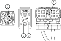
Measure resistance between 9-Way Diagnostic Connector Pin D and 38-Way Vehicle Harness Connector Pin 2. Record reading(s) in table.
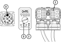
Compare reading(s) in table.
If readings are in range, refer to Service Bulletin TAIB-0886. Go to Step V
If readings are out of range, refer to OEM guidelines for repair or replacement of vehicle J1939 Data Link. Go to Step V
| Pins | Range | Reading(s) |
|---|---|---|
| C to 3 | 0.0–0.3 ohms | |
| D to 2 | 0.0–0.3 ohms |
Key off.
Disconnect 38-Way Vehicle Harness Connector from TECU.
Measure resistance between 9-Way Diagnostic Connector Pin F and 38-Way Vehicle Harness Connector Pin 3. Record reading(s) in table.
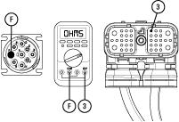
Measure resistance between 9-Way Diagnostic Connector Pin G and 38-Way Vehicle Harness Connector Pin 2. Record reading(s) in table.
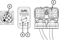
Compare reading(s) in table.
If readings are in range, refer to Service Bulletin TAIB-0886. Go to Step V
If readings are out of range, refer to OEM guidelines for repair or replacement of vehicle J1939 Data Link. Go to Step V
| Pins | Range | Reading(s) |
|---|---|---|
| F to 3 | 0.0–0.3 ohms | |
| G to 2 | 0.0–0.3 ohms |
Key off.
Reconnect all connectors and verify that all components are properly installed.
Key on with engine off.
Clear fault codes using ServiceRanger.
Drive vehicle and attempt to reset the code or duplicate the previous complaint.
Check for fault codes using ServiceRanger.
If no fault codes set Active during the test drive and vehicle operates properly, test complete.
If a fault code is set Active during the test drive, troubleshoot per Fault Code Isolation Procedure Index.
If no fault codes set Active and the vehicle complaint is duplicated, refer to Contact Information and contact Eaton for further diagnostics.