Endurant HD
TRTS0950 EN-US
|
August 2025 - A
Eaton Breakout Box and Eaton Diagnostic Adapter Procedure
Overview
This procedure describes how to use the Eaton Breakout Box (RR1029TR). This diagnostic tool eliminates the need for a diagnostic pin kit and simplifies access to component electrical circuits.
 |
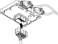
1. Eaton Breakout Box (RR1029TR) 2. 74-Way EDA Transmission Control Module Connector - part of RR1029TR 3. 74-Way EDA Transmission Harness Connector - part of RR1029TR |
Troubleshooting TCM Signals with the Eaton Breakout Box
- Key off.
- Remove the TCM from the MTM with the 20-Way TCM Vehicle Harness Connector and 20-Way TCM Body Harness Connector connected.

- Connect the Eaton Breakout Box with 74-Way Eaton Diagnostic Adapter to the TCM side of the 74-Way Transmission Harness Connector and hand tighten TCM jack screw.

- Key on.
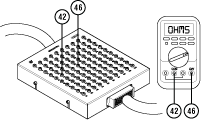
- Measure voltage at the Eaton Breakout Box between Pin 42 and Pin 46.

Troubleshooting Internal Components and Circuits with the Eaton Breakout Box
- Key off.
- Remove the TCM from the MTM with the 20-Way TCM Vehicle Harness Connector and 20-Way TCM Body Harness Connector connected..

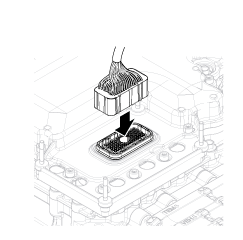
- Connect the Eaton Breakout Box with 74-Way Eaton Diagnostic Adapter to the MTM side of the 74-Way Transmission Harness Connector and hand tighten jack screw on connector.

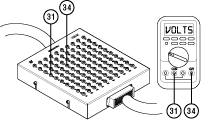
- Measure resistance at the Eaton Breakout Box between Pin 31 and Pin 34.
