J1939 Vehicle Data Link Test
Overview
This symptom driven test is performed if the J1939 Vehicle Data Link is failing to function in some way without setting transmission Fault Code 115. Proper operation of the J1939 Vehicle Data Link is critical for proper transmission operation.
Detection
- Various communication problems between vehicle ECUs.
- ServiceRanger or other diagnostic software may not be able to communicate with TCM or vehicle ECUs.
- If vehicle is configured for the J1939 Start Enable feature the engine may not crank.
Possible Causes
- J1939 Vehicle Data Link
- Wiring shorted to ground, shorted to power or open
- Bent, spread, corroded or loose terminals
- Excessive electrical noise
- Missing or additional terminating resistors
- Various Vehicle ECUs
- Internal Failure
- Loss of Power Supply to ECU
- Poor connection to J1939 Vehicle Data Link
- Wiring shorted to ground, shorted to power or open
J1939 Vehicle Data Link Test
Set vehicle parking brake and chock wheels.
Key on with engine off.
Connect ServiceRanger.
Retrieve and record the transmission fault codes and FMIs, and their occurrences and timestamps.
If a vehicle/engine fault code(s) is Active, contact OEM for further diagnostic instructions.
If Fault Code 115 is Active or Inactive, troubleshoot per Fault Code Isolation Procedure Index.
If ServiceRanger does not connect to the Transmission Control Module (TCM), Go to Step B
Key off.
Refer to the OEM and identify the TCM location on the Vehicle Primary Data Link (J1939A) at the 9-Way Diagnostic Connector.
If the TCM is on 9-Way Diagnostic Connector Pin C and Pin D, Go to Step G
If the TCM is on 9-Way Diagnostic Connector Pin F and Pin G, Go to Step C
Key on with engine off.
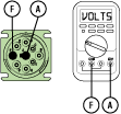
Measure voltage between 9-Way Diagnostic Connector Pin F and Pin A. Record reading in table.
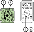
Measure voltage between 9-Way Diagnostic Connector Pin G and Pin A. Record reading in table.
Record the total voltage by adding together the voltage readings.
Compare reading(s) in table.
If readings are in range, Go to Step D
If readings are out of range, refer to OEM guidelines for repair or replacement of vehicle Primary Data Link (J1939 A). Go to Step V
| Pins | Range | Reading(s) |
|---|---|---|
| F to A | N/A | |
| G to A | N/A | + |
| Total Voltage | 4.5–5.5 V | = |
Key off.
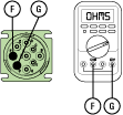
Measure resistance between 9-Way Diagnostic Connector Pin F and Pin G. Record reading in table.
Compare reading(s) in table.
If readings are out of range, refer to OEM guidelines for repair or replacement of vehicle Primary Data Link (J1939 A). Go to Step V
If readings are in range, Go to Step E
| Pins | Range | Reading(s) |
|---|---|---|
| F to G | 50–70 Ohms |
Key off.
Disconnect the 20-way TCM Vehicle Harness Connector.
Inspect the 20-Way TCM Vehicle Harness Connector, verify the connector is free from contamination and corrosion; the terminals are not bent, spread or loose; and there is no damage to the connector body.
Inspect the TCM side of the 20-Way TCM Vehicle Harness Connector, verify the connector is free from contamination and corrosion; the terminals are not bent, spread or loose; and there is no damage to the connector body.
If contamination or damage is found, refer to OEM guidelines for repair or replacement of the 20-Way TCM Vehicle Harness Connector. Go to Step V
If no contamination or damage is found, Go to Step F
Key off.
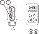
Measure resistance between 20-Way TCM Vehicle Harness Connector Pin 11 and Pin 12. Record reading in table.
Reconnect 20-Way TCM Vehicle Harness Connector
Compare reading(s) in table.
If readings are out of range, refer to OEM guidelines for repair or replacement of vehicle Primary Data Link (J1939 A). Go to Step V
If readings are in range, Go to Step I
| Pins | Range | Reading(s) |
|---|---|---|
| 11 to 12 | 50–70 Ohms |
Key on with engine off.
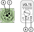
Measure voltage between 9-Way Diagnostic Connector Pin C and Pin A. Record reading in table.
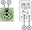
Measure voltage between 9-Way Diagnostic Connector Pin D and Pin A. Record reading in table.
Record the total voltage by adding together the voltage readings.
Compare reading(s) in table.
If readings are in range, Go to Step H
If readings are out of range, refer to OEM guidelines for repair or replacement of vehicle Primary Data Link (J1939 A). Go to Step V
| Pins | Range | Reading(s) |
|---|---|---|
| C to A | N/A | |
| D to A | N/A | + |
| Total Voltage | 4.5–5.5 V | = |
Key off.
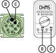
Measure resistance between 9-Way Diagnostic Connector Pin C and Pin D. Record reading in table.
Compare reading(s) in table.
If readings are out of range, refer to OEM guidelines for repair or replacement of vehicle Primary Data Link (J1939 A). Go to Step V
If readings are in range, Go to Step I
| Pins | Range | Reading(s) |
|---|---|---|
| C to D | 50–70 Ohms |
Key off.
Disconnect the 20-Way TCM Vehicle Harness Connector.
Inspect the 20-Way TCM Vehicle Harness Connector, verify the connector is free from contamination and corrosion; the terminals are not bent, spread or loose; and there is no damage to the connector body.
Inspect the TCM side of the 20-Way TCM Vehicle Harness Connector, verify the connector is free from contamination and corrosion; the terminals are not bent, spread or loose; and there is no damage to the connector body.
If contamination or damage is found, refer to OEM guidelines for repair or replacement of the 20-Way TCM Vehicle Harness Connector. Go to Step V
If no contamination or damage is found, Go to Step J
Key off.
Measure resistance between 20-Way TCM Vehicle Harness Connector Pin 11 and Pin 12. Record reading in table.

Reconnect 20-Way TCM Vehicle Harness Connector.
Compare reading(s) in table.
If readings are out of range, refer to OEM guidelines for repair or replacement of vehicle Primary Data Link (J1939 A). Go to Step V
If readings are in range, Go to Step K
| Pins | Range | Reading(s) |
|---|---|---|
| 11 to 12 | 50–70 Ohms |
Key off.
Reconnect all connectors and verify that all components are properly installed.
Key on with engine off.
Connect ServiceRanger.
Go To “Data Monitor”.
Select “Components” tab.
Monitor the roster of vehicle ECUs currently communicating on the Primary Data Link (J1939 A).
Compare this list to the roster of vehicle ECUs that should be communicating on the Primary Data Link (J1939 A).
Note: Contact OEM for information about which vehicle ECUs should be on the Primary Data Link (J1939 A).
If no vehicle ECUs are present on the ServiceRanger roster, Go to Step L
If all vehicle ECUs are present on the ServiceRanger roster, no problem was found. Test complete. Contact OEM for further diagnostic instructions.
If a vehicle ECU is missing from the ServiceRanger roster, investigate that device to verify that it is properly powered and wired to the Primary Data Link (J1939 A). Refer to OEM guidelines for repair or replacement. Go to Step V
Key on with engine off.
Connect ServiceRanger.
Go To “Data Monitor”.
Select “Components” tab.
Monitor the roster of vehicle ECUs currently communicating on the Primary Data Link (J1939 A).
Individually remove each vehicle ECU from the Primary Data Link (J1939 A).
After removing each device, monitor the ServiceRanger ECU roster.
If the removal of an ECU from the Primary Data Link (J1939 A) allows Other Vehicle ECU(s) to appear in the ServiceRanger ECU roster, the removed ECU may have an internal failure preventing communication over the Primary Data Link (J1939 A). Refer to OEM guidelines for repair or replacement. Go to Step V
If no problems are found, Contact OEM for further diagnostic instructions.
Key off.
Reconnect all connectors and verify that all components are properly installed.
Key on with engine off.
Connect ServiceRanger.
Go to “Fault Codes”.
Select “Clear All Faults”.
Operate vehicle and attempt to reset the fault code or duplicate the previous complaint.
Check for fault codes using ServiceRanger.
If no fault codes set and the vehicle operates properly, test complete.
If Fault Code 115 sets Active during operation, Go to Step A
If a fault code other than 115 sets Active, troubleshoot per the Fault Code Isolation Procedure Index.