Power-Up Sequence
Overview
This symptom-driven test is performed if the transmission system fails to fully power up at ignition on.
Detection
- Display may be blank.
- Engine may not crank.
- ServiceRanger may not connect to Transmission Control Module (TCM).
Note: Fault codes that set give additional information about performance issues detected on the vehicle. If a unit has an Active fault code, or repeated occurrences of an Inactive fault code, troubleshoot per the Fault Code Isolation Procedure Index.
Possible Causes
- Vehicle Power Supply Wiring
- Poor power or ground supply to TCM
- Bent, spread, corroded or loose terminals
- Wires grounded, open or shorted
- Vehicle Batteries
- Internal failure
- Vehicle Primary Data Link (J1939 A)
- Wiring shorted to ground, shorted to power or open
- Bent, spread, or loose terminals
- TCM
- Internal Failure
Component Identification
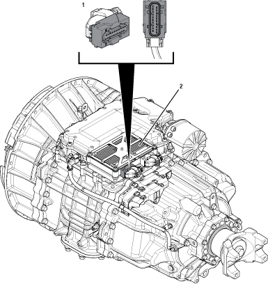 |
1. 20-Way TCM Vehicle Harness Connector 2. Transmission Control Module (TCM) |
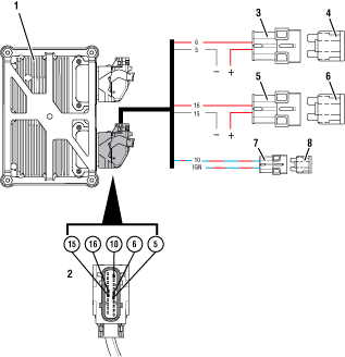 |
1. Transmission Control Module (TCM) 2. 20-Way TCM Vehicle Harness Connector 3. In-line Fuse Holder Battery Voltage1 4. 15-amp Fuse Battery Voltage1 5. In-line Fuse Holder Battery Voltage2 6. 15-amp Fuse Battery Voltage2 7. In-line Fuse Holder 8. 10-amp Fuse |
 |
Power-Up Sequence Test
Set vehicle parking brake and chock wheels.
Key off.
Inspect the vehicle charging/battery system and connections, verify the connectors are free from contamination and corrosion; the terminals are not bent, spread or loose; and there is no damage to the connector bodies.
Inspect the transmission 10-amp Ignition and both 15-amp fuses/fusible links, verify the connectors are free from contamination and corrosion; the terminals are not bent, spread or loose; and there is no damage to the connector bodies.
Inspect the vehicle harness and connectors from the power supply to the 20-Way TCM Vehicle Harness Connector, verify the connectors are free from contamination and corrosion; the terminals are not bent, spread or loose; and there is no damage to the connector bodies or harness.
Note: Some chassis use a power and ground distribution block separate from the battery or may route power and ground to the starter. Be sure to clean and inspect connections at this location and at the battery.
Measure voltage across all batteries. Record reading in table.
Compare reading(s) in table.
If readings are out of range or damage is found, refer to OEM guidelines for repair or replacement of the vehicle charging/battery system, vehicle harness and/or 20-Way TCM Vehicle Harness Connector. Test complete.
If readings are in range and no damage is found, Go to Step B
| Range | Reading(s) |
|---|---|
| 11–15 V |
Key off.
Disconnect the 20-Way TCM Vehicle Harness Connector.
Inspect the 20-Way TCM Vehicle Harness Connector, verify the connector is free from contamination and corrosion; the terminals are not bent, spread or loose; and there is no damage to the connector body.
Inspect the TCM side of the 20-Way TCM Vehicle Harness Connector, verify the connector is free from contamination and corrosion; the terminals are not bent, spread or loose; and there is no damage to the connector body.
Measure voltage between 20-Way TCM Vehicle Harness Connector Pin 6 (Battery positive) and Pin 5 (Battery negative). Record reading in table.
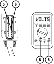
Compare reading(s) in table.
If readings are in range, Go to Step C
If readings are out of range, refer to OEM guidelines for repair or replacement of the power supply to the TCM.
| Pins | Range | Reading(s) |
|---|---|---|
| 5 to 6 | 11–15 V |
Key off.
Measure voltage between 20-Way TCM Vehicle Harness Connector Pin 16 (Battery positive) and Pin 15 (Battery negative). Record reading in table.
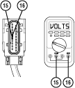
Compare reading(s) in table.
If readings are in range, Go to Step D
If readings are out of range, refer to OEM guidelines for repair or replacement of the power supply to the TCM.
| Pins | Range | Reading(s) |
|---|---|---|
| 15 to 16 | 11–15 V |
Key on with engine off.
Measure voltage between 20-Way TCM Vehicle Harness Connector Pin 10 (Ignition positive) and Pin 5 (Battery negative). Record reading in table.
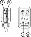
Compare reading(s) in table.
If readings are in range, Go to Step E
If readings are out of range, refer to OEM guidelines for repair or replacement of ignition voltage supply to TCM.
| Ignition State | Pins | Range | Reading(s) |
|---|---|---|---|
| Key on | 5 to 10 | 11–15 V |
Key off.
Disconnect the 20-Way TCM Vehicle Harness Connector.
Measure resistance between 20-Way TCM Vehicle Harness Connector Pin 11 and Pin 12. Record reading in table.
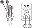
Reconnect 20-Way TCM Vehicle Harness Connector.
Compare reading(s) in table.
If readings are out of range, refer to OEM guidelines for repair or replacement of vehicle Primary Data Link (J1939 A). Go to Step V
If readings are in range, Go to Step F
| Ignition State | Pins | Range | Reading(s) |
|---|---|---|---|
| Key off | 11 to 12 | 50-70 Ohms |
Key off.
Reconnect all connectors and verify that all components are properly installed.
Key on.
Connect ServiceRanger.
Retrieve and record the transmission fault codes, FMIs, occurrences, and timestamps.
If ServiceRanger connects and a fault code is Active, Go to Step G
If ServiceRanger connects and no fault code is Active, an intermittent wiring issue exists within the Vehicle Harness between the:
- Vehicle power supply and 20-Way TCM Vehicle Harness Connector.
- or
- Vehicle Primary Data Link (J1939 A) and the 20-Way TCM Vehicle Harness Connector.
- Refer to OEM guidelines for repair or replacement. Go to Step V
If ServiceRanger does not connect, replace the TCM, Go to Step V
Determine the fault code to troubleshoot first by using the priority index below (with 1 highest priority and 4 least priority).
- Priority 1: Vehicle Interface Fault Codes 100-199
- Priority 2: Component Fault Codes 200-499
- Priority 3: System Fault Codes 500-899
- Priority 4: Feature Fault Codes 900-999
Go to the Fault Code Isolation Procedure Index and troubleshoot the fault code with the highest priority level.
Key off.
Reconnect all connectors and verify that all components are properly installed.
Key on.
Clear fault codes using ServiceRanger.
Operate vehicle and attempt to reset the code or duplicate the previous complaint.
Check for fault codes using ServiceRanger.
If no codes set and the vehicle operates properly, test complete.
If a fault code sets, troubleshoot per Fault Code Isolation Procedure Index.