Endurant HD
TRTS0950 EN-US
|
February 2026 - A
Manually Actuate Rail E Procedure
Special Instructions
None
Special Tools
- Mechanical Diagnostic Kit (RR2011TR)
Component Identification
 |
1. MTM Cap Screws, Long (x4) - 13 mm 2. MTM Cap Screws, Special (x2) - 15 mm 3. MTM Cap Screws (x14) - 13 mm 4. Mechatronic Transmission Module (MTM) 5. Main Housing 6. Output Speed Sensor |
Procedure – Manually Actuate Rail E
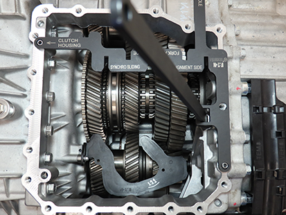
Install the MTM Alignment Tool (RR1086TR-1) on the main housing.

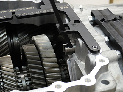
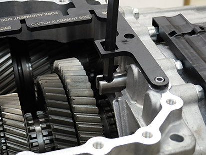
Using the Rail E Lever, move Rail E to neutral.


Return to troubleshooting procedure.