Start Enable Relay Contact Test
Overview
This symptom-driven test is performed if the engine does not crank with the Driver Interface Device in neutral, the transmission confirming neutral, and there are no Active or Inactive fault codes.
Detection
- Engine does not crank with the transmission in park or neutral.
- Engine cranks with the transmission in a non-neutral position.
Note: If the engine was shut off with the transmission in gear, confirm the vehicle air supply pressure is in range and the vehicle parking brake is set or service brake is depressed when attempting to start the engine.
Possible Causes
- Start Enable Type
- Mis-configured in the TCM
- J1939 start enable message not received by vehicle
- Start Enable Relay
- Internal failure
- Start Enable Relay Circuit Wiring
- Bypassed or “jumped” Start Enable Relay circuit
- Bent, spread, corroded or loose terminals
- Wiring shorted to ground, shorted to power or open
Component Identification
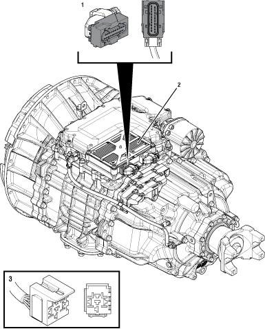 |
1. 20-Way TCM Vehicle Harness Connector 2. Transmission Control Module (TCM) 3. 5-Way Start Enable Relay Socket |
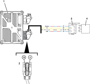 |
1. Transmission Control Module (TCM) 2. 20-Way TCM Vehicle Harness Connector 3. 5-Way Start Enable Relay Socket 4. 5-Way Start Enable Relay |
 |
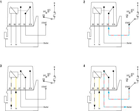 |
Start Enable Relay Circuit States (Normally Open) 1. Open Relay - Key On and Transmission is Unable to Confirm Neutral 2. Open Relay - Key Start and Transmission is Unable to Confirm Neutral 3. Closed Relay - Key On and Transmission Confirmed in Neutral 4. Closed Relay - Key Start and Transmission Confirmed in Neutral |
 |
Start Enable Relay Contact Test
Set vehicle parking brake and chock wheels.
Key on with engine off.
Verify that the Transmission Driver Interface Device is in the Neutral (N) position.
Verify the transmission is in Neutral, indicated by an “N” in the display.
If the display indicates “N”, Go to Step B
If the display does not indicate “N”, contact Eaton Cummins Automated Transmission Technologies at 1-800-826-HELP (4357) for further diagnostic instructions. Go to Step V
Key off.
Inspect vehicle starting/charging/battery system per OEM guidelines.
If a fault was found, refer to OEM guidelines for repair or replacement of the vehicle starting/charging/battery system. Go to Step V
If no fault found, Go to Step C
Inspect the vehicle to determine if the Start Enable function is performed through a physically hard- wired relay or a transmission message broadcast over the J1939 Data Link.
Note: Refer to OEM regarding vehicle Start Enable type system.
If a Start Enable message is sent over J1939 by the TCM, Go to Step D
If a Start Enable Relay is hardwired to the TCM, Go to Step G
Key on with engine off.
Connect ServiceRanger.
Go To “Configuration”.
Select “Vehicle”.
Record the “Start Enable Type” “Current Value” in table.
Confirm the configuration matches the vehicle’s start enable system.
Compare reading(s) in table.
If readings are in range, Go to Step E
If readings are out of range, select “J1939” from the “New Value” drop down, select “Apply” and follow on-screen prompts. Go to Step V
| Parameter | Range | Reading(s) |
|---|---|---|
| Start Enable Type | J1939 |
Key on with engine off.
Verify that the Transmission Driver Interface Device is in Neutral (N).
Verify the transmission is in Neutral, indicated by an “N” in the display.
Depress and hold the service brake, attempt to crank the engine.
If engine cranks, Go to Step F
If the engine does not crank and the display indicates “N”, refer to OEM guidelines for repair or replacement of the vehicle starting/charging/battery system. Go to Step V
Key on with engine off.
Place the Transmission Driver Interface Device in a non-Neutral position.
Depress and hold the service brake, attempt to crank the engine.
Return the Transmission Driver Interface Device to Neutral (N).
If the engine cranks, a vehicle system allowed the engine to crank when the transmission system requested cranking disabled. Contact OEM for further diagnostic instructions. Go to Step V
If the engine does not crank, no fault was found. Test Complete. If additional troubleshooting is required, contact OEM for additional information about this system. Go to Step V
Key on with engine off.
Connect ServiceRanger.
Go To “Configuration”.
Select “Vehicle”.
Record the “Start Enable Type” “Current Value” in table.
Confirm the configuration matches the vehicle’s start enable system.
Compare reading(s) in table.
If readings are in range, Go to Step H
If readings are out of range, select “Relay” from the “New Value” drop down, select “Apply” and follow on-screen prompts. Go to Step V
| Parameter | Range | Reading(s) |
|---|---|---|
| Start Enable Type | Relay |
Key on with engine off.
Verify that the Transmission Driver Interface Device is in Neutral (N).
Verify the transmission is in Neutral, indicated by an “N” in the display.
Depress and hold the service brake, attempt to crank the engine.
If the engine cranks, Go to Step I
If the engine does not crank, Go to Step L
Key on with engine off.
Place the Transmission Driver Interface Device in a non-Neutral position.
Depress and hold the service brake, attempt to crank the engine.
Return the Transmission Driver Interface Device to Neutral (N).
If the engine cranks, Go to Step J
If the engine does not crank, Go to Step K
Key on with engine off.
Remove the Start Enable Relay.
Key on with engine off.
Place the Transmission Driver Interface Device in a non-Neutral position.
Depress and hold the service brake, attempt to crank the engine.
Return the Transmission Driver Interface Device to Neutral (N).
If the engine cranks, refer to OEM guidelines for repair or replacement of Start Enable Relay wiring. Go to Step V
If the engine does not crank, replace the Start Enable Relay. Go to Step V
Key off.
Refer to OEM wiring diagrams and verify the Start Enable Relay wiring is properly installed.
Disconnect the Start Enable Relay from the socket.
Measure resistance between 20-Way TCM Vehicle Harness Connector Pin 14 and Start Enable Relay Socket Pin 86. Record reading in table.
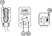
Measure resistance between 20-Way TCM Vehicle Harness Connector Pin 4 and Start Enable Relay Socket Pin 85. Record reading in table.
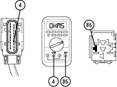
Compare reading(s) in table.
If readings are in range, Go to Step L
If readings are out of range, refer to OEM guidelines for repair or replacement of the Start Enable Relay wiring. Go to Step V
| Pins | Range | Reading(s) |
|---|---|---|
| VH 14 to SER 86 | 0.0–0.3 ohms | |
| VH 4 to SER 85 | 0.0–0.3 ohms |
Set vehicle parking brake and chock wheels.
Key on with engine off.
Verify the Transmission Driver Interface Device is in the Neutral (N) position.
Verify the transmission is in Neutral indicated by an “N” in the display.
Key off.
Remove the Start Enable Relay.
Place a jumper wire between socket Pin 30 and Pin 87.

Key on with engine off.
Verify that the Transmission Driver Interface Device is in Neutral (N) position.
Verify the transmission is in Neutral, indicated by an “N” in the display.
Depress and hold the service brake, attempt to crank the engine.
If the engine cranks, replace the Start Enable Relay. Go to Step V
If the engine does not crank, contact OEM for further diagnostic instructions. Go to Step V
Key off.
Reconnect all connectors and verify that all components are properly installed.
Key on with engine off.
Clear fault codes using ServiceRanger.
Verify that the Driver Interface Device is in Neutral (N).
Verify the transmission is in Neutral, indicated by an “N” in the display.
Test the Start Enable system by attempting to crank the Starter multiple times. Verify that the starting system operates properly.
Check for fault codes using ServiceRanger.
If no codes set and the engine cranks, test complete.
If the engine does not crank and a fault code sets, troubleshoot per Fault Code Isolation Procedure Index.
If the engine does not crank and no fault codes set, contact OEM for further diagnostic instructions.