Fault Code 135: Primary Shift Device (J1939)
J1939: SA 3 SPN 751 FMI 2, 9, 11, 12, 13, 14, 19
Overview
The Transmission Control Module (TCM) is configured to accept Primary Shift Device messages from the transmission driver interface device over the Primary Data Link (J1939A). This information is used to determine transmission operation.
A Secondary Shift Device request signal from the transmission driver interface device is also provided on a separate hardwired circuit. The Secondary Shift Device request signal allows a driver to engage the transmission into a Shift Mode in the event the Primary Shift Device message is not available.
The Primary Data Link (J1939A), transmission driver interface device, and Secondary Shift Device hardwired circuit and wiring are installed by the OEM and connect to the TCM through the 20-Way TCM Vehicle Harness Connector.
Detection
The TCM monitors Primary Shift Device messages. If messages are not received or are invalid, the fault is set Active.
Conditions to Set Fault Code Active
FMI 2 – Data Erratic: Primary Shift Device message out of range for 5 seconds.
FMI 9 – Abnormal Update Rate: Primary Shift Device message not received for 5 seconds.
FMI 11 – Root Cause Unknown: Primary and Secondary Shift Device values do not match for 1 second.
FMI 12 – Bad Intelligent Device: Primary Shift Device request in opposite direction of vehicle travel at a speed greater than allowable shuttle shifting speed.
FMI 13 – Out Of Calibration: Primary Shift Device message not available for 5 seconds.
FMI 14 – Special Instructions: Delayed gear engagement after shift mode change.
FMI 19 – Received Network Data In Error: Primary Shift Device messages invalid for 5 seconds.
Fallback
FMI 2, 9, 13, 19:
- Amber warning lamp on
- If vehicle is moving and fault codes 135 and 145 are Active:
- Non-Neutral modes prohibited
- PTO mode prohibited
- Hill Start Aid prohibited
- Engine cranking prohibited
- If vehicle is not moving and fault codes 135 and 145 are Active:
- Urge to Move and Creep Mode prohibited
- Non-Neutral modes prohibited
- PTO mode prohibited
- Hill Start Aid prohibited
- Engine cranking prohibited
- If vehicle is moving:
- Red stop lamp on
FMI 11:
- Amber warning lamp on
- Engine cranking prohibited
- Non-Neutral modes prohibited
- PTO mode prohibited
- Hill Start Aid prohibited
- If vehicle is moving:
- Red stop lamp on
FMI 12:
- Inertia Brake activation prohibited
- Upshifts prohibited
- Clutch engagements prohibited
FMI 14:
- Urge to Move and Creep Mode prohibited
- Non-Neutral modes prohibited
- PTO mode prohibited
Conditions to Set Fault Code Inactive
FMI 2: Primary Shift Device messages in range for 10 seconds.
FMI 9, 19: Primary Shift Device messages received and valid for 10 seconds.
FMI 11: Primary and Secondary Shift Device values match for 1 second.
FMI 12, 14: Key cycle and fault condition no longer exist.
FMI 13: Primary Shift Device messages received and valid for 1 second.
Possible Causes
FMI 2, 9, 11, 13, 19:
- Vehicle Components
- Transmission driver interface device internal failure
- Vehicle Harness - Power supply, Primary Data Link (J1939A) and Secondary Shift Device request circuit
- Wiring shorted to power, shorted to ground or open
- Terminals bent, spread, corroded, or loose
FMI 12, 14:
- TCM
- Software issue
- Internal failure
Note: Refer to OEM for troubleshooting a failed system.
Additional Tools
- Endurant XD Service Manual TRSM0960
- Digital Volt Ohm Meter (DVOM)
Component Identification
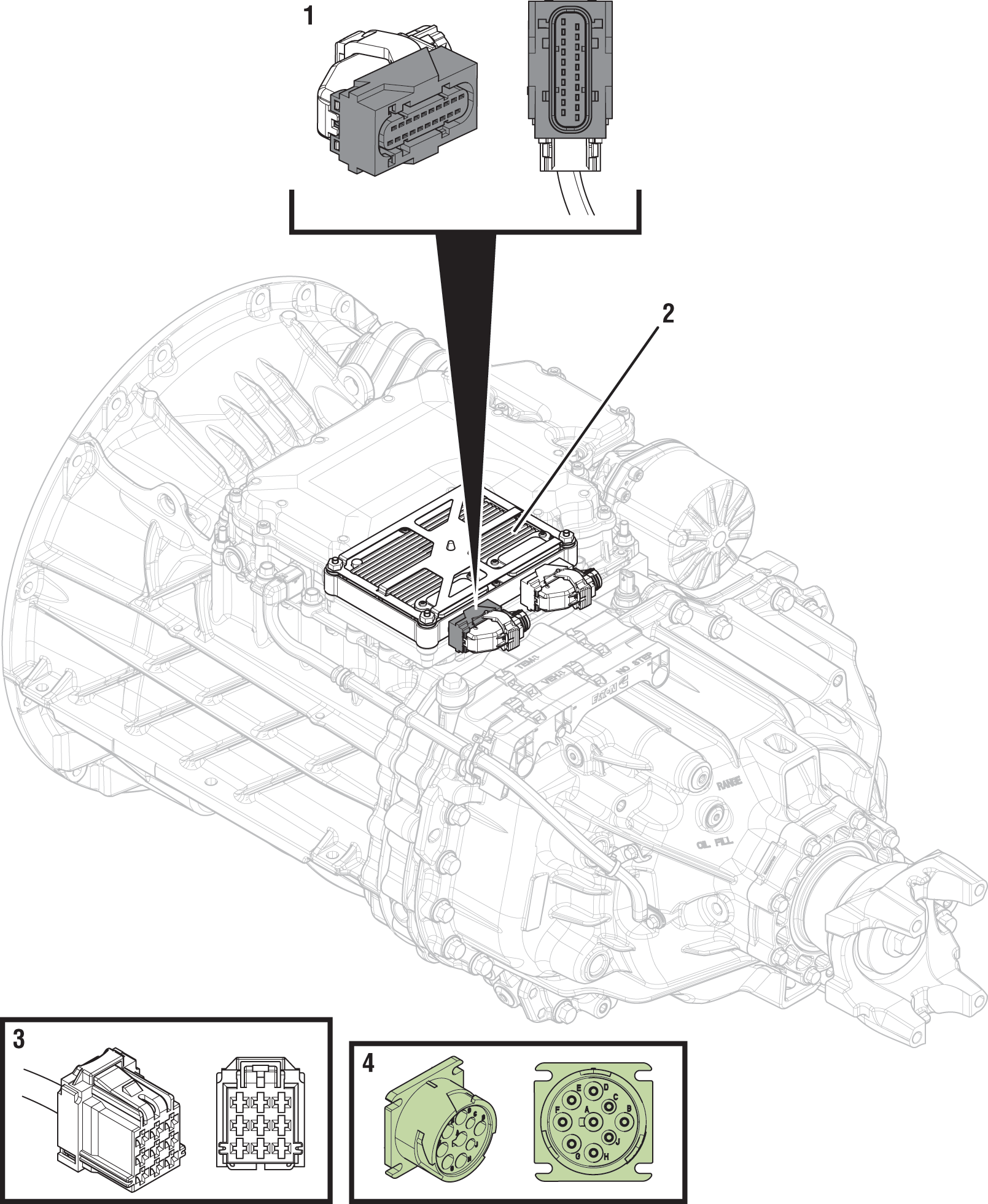 |
1. 20-Way TCM Vehicle Harness Connector 2. Transmission Control Module (TCM) 3. OEM Transmission Driver Interface Device Connector (OEM Specific) 4. 9-Way Type 2 Diagnostic Connector (In Cab) |
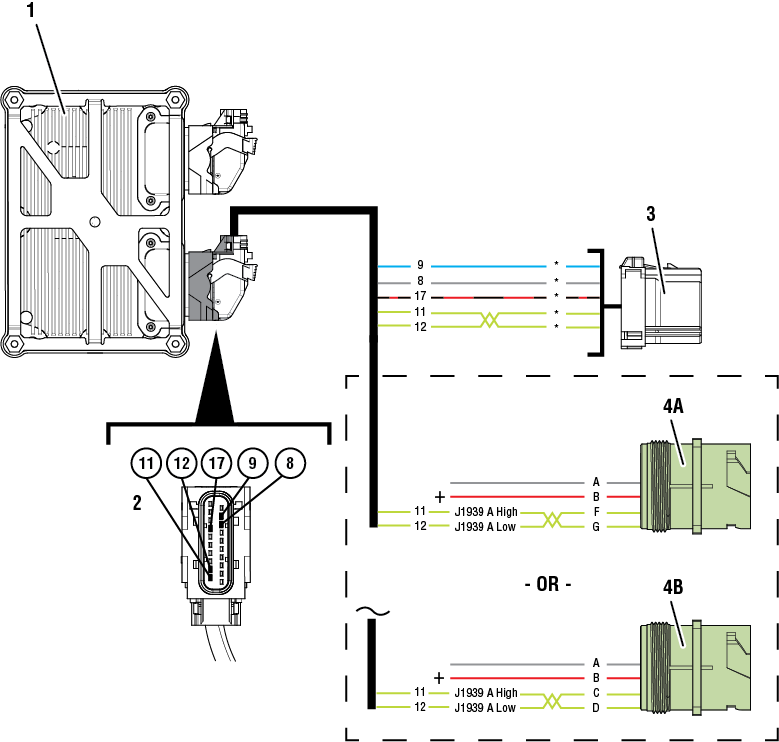 |
1. Transmission Control Module (TCM) 2. 20-Way TCM Vehicle Harness Connector 3. OEM Transmission Driver Interface Device Connector (OEM Specific) 4A. 9-Way Type 2 Diagnostic Connector (OEM-Specific Primary Data Link FG) 4B. 9-Way Type 2 Diagnostic Connector (OEM-Specific Primary Data Link CD) *Refer to OEM wiring diagrams and connector views to verify circuit locations and descriptions. |
 |
Fault Code 135 Troubleshooting
Set vehicle parking brake and chock wheels.
Record transmission fault codes, FMIs, occurrences, and timestamps from Service Activity Report created during the Diagnostic Procedure.
If Fault Code 135 is Inactive and there are other Active vehicle or transmission fault codes, troubleshoot all Active fault codes. Go to Step V
If Fault Code 135 FMI 2, 9, 19 is Active or Inactive, Go to Step B
If Fault Code 135 FMI 11 is Active or Inactive, Go to Step E
If Fault Code 135 FMI 12, 14 is Active or Inactive, Contact Eaton Cummins Automated Transmission Technologies for further diagnostic instructions. For Help Line phone numbers, go to Contact Information. Go to Step V
If Fault Code 135 FMI 13 is Active, configure Driver Interface Type in TCM using ServiceRanger. Go to Step V
If Fault Code 135 FMI 13 is Inactive, Driver Interface Type is configured in TCM. Go to Step V
Key off.
Disconnect OEM transmission driver interface device connector.
Inspect OEM transmission driver interface device connector, verify connector is free from contamination and corrosion; terminals are not bent, spread or loose; and there is no damage to connector body.
Key on with engine off.
Measure voltage between OEM transmission driver interface device connector TCM supplied 12v (+) and Pin 2 TCM supplied ground (-). Record reading in table.
Note: Refer to OEM transmission driver interface device wiring diagrams.

Compare reading(s) in table.
Note: Refer to OEM wiring diagrams and connector views to verify circuit locations and descriptions.
If readings are in range, Go to Step C
If readings are out of range, refer to OEM guidelines for repair or replacement of transmission driver interface device power supply circuits between OEM transmission driver interface device connector and 20-Way TCM Vehicle Connector. Go to Step V
| Pins | Range | Reading(s) |
|---|---|---|
| TCM Supplied 12V to TCM Supplied Ground | 11–13 V |
Key on with engine off.
Measure voltage between 9-Way transmission driver interface device connector J1939 Data Link High and 9-Way Diagnostic Connector Pin A (ground). Record reading in table.
Note: Refer to OEM transmission driver interface device wiring diagrams.
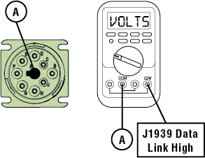
Measure voltage between OEM transmission driver interface device connector J1939 Data Link Low and 9-Way Diagnostic Connector Pin A (ground). Record reading in table.
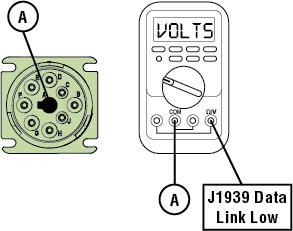
Compare reading(s) in table.
Note: Refer to OEM wiring diagrams and connector views to verify circuit locations and descriptions.
If readings are in range, Go to Step D
If readings are out of range, refer to OEM guidelines for repair or replacement of vehicle J1939 Data Link. Go to Step V
| Pins | Range | Reading(s) |
|---|---|---|
| J1939 Data Link High | 2.25–2.75 V | |
| J1939 Data Link Low | 2.25–2.75 V |
Key off.
Reconnect all connectors and verify all components are properly installed.
Key on with engine off.
Connect ServiceRanger.
Go To “Fault Codes”.
Retrieve and record fault codes, FMIs, occurrences and timestamps.
If Fault Code 135 is Active, refer to OEM guidelines for repair or replacement of the transmission driver interface device. Go to Step V
If Fault Code 135 is Inactive, the intermittent nature of the fault makes it likely one of the following conditions exists. Contact OEM for further diagnostic instructions. Go to Step V
- Wiring problem between transmission driver interface device and 20-Way TCM Vehicle Connector.
- Wiring problem between Primary Data Link (J1939A) and transmission driver interface device.
- Transmission driver interface device may intermittently not be powering up.
Key off.
Disconnect OEM transmission driver interface device connector.
Inspect OEM transmission driver interface device connector, verify connector is free from contamination and corrosion; terminals are not bent, spread or loose; and there is no damage to connector body.
Key on with engine off.
Measure voltage between OEM transmission driver interface device connector TCM supplied 12v (+) and TCM supplied ground (-). Record reading in table.
Note: Refer to OEM transmission driver interface device wiring diagrams.

Compare reading(s) in table.
Note: Refer to OEM wiring diagrams and connector views to verify circuit locations and descriptions.
If readings are in range, Go to Step F
If readings are out of range, refer to OEM guidelines for repair or replacement of transmission driver interface device power supply circuits between OEM transmission driver interface device connector and 20-Way TCM Vehicle Connector. Go to Step V
| Pins | Range | Reading(s) |
|---|---|---|
| TCM Supplied 12V to TCM Supplied Ground | 11–13 V |
Key off.
Disconnect 20-Way TCM Vehicle Harness Connector from TCM.
Inspect 20-Way TCM Vehicle Harness Connector, verify connector is free from contamination and corrosion; terminals are not bent, spread or loose; and there is no damage to connector body.
Measure resistance between the OEM Driver Interface Device Connector Secondary Shift Device Request Circuit (SSDRC) and 20-Way TCM Vehicle Harness Connector Pin 9. Record reading in table.
Note: Refer to OEM wiring diagrams.
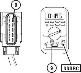
Measure resistance between the OEM Driver Interface Device Connector Secondary Shift Device Request Circuit (SSDRC) and Ground. Record reading in table.
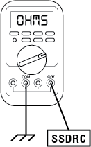
Compare reading(s) in table.
Note: Refer to OEM wiring diagrams and connector views to verify circuit locations and descriptions.
If readings are in range, Go to Step G
If readings are out of range, refer to OEM guidelines for repair or replacement of the SSDRC between the OTM Driver Interface Device Connector and the 20-Way TCM Vehicle Harness Connector. Go to Step V
| Pins | Range | Reading(s) |
|---|---|---|
| SSRDC to 9 | 0.0 –0.3 Ohms | |
| SSDRC to Ground | Open Circuit (OL) |
Key off.
Reconnect all connectors and verify that all components are properly installed.
Key on with engine off.
Connect ServiceRanger.
Go To “Fault Codes”.
Retrieve and record fault codes, FMIs, occurrences and timestamps.
If Fault Code 135 is Active, refer to OEM guidelines for repair or replacement of the transmission driver interface device. Go to Step V
If Fault Code 135 is Inactive, no problem was found. The intermittent nature of the fault makes it likely that the problem is in one of the following. Contact OEM for further diagnostic instructions. Go to Step V
- Transmission driver interface device
- Secondary Shift Device hardwired circuit between transmission driver interface device and 20-Way TCM Vehicle Connector.
- Primary Data link (J1939A) wiring to transmission driver interface device.
- Power and ground supply wiring to transmission driver interface device from 20-Way TCM Vehicle Connector.
Key off.
Reconnect all connectors and verify all components are properly installed.
Key on with engine off.
Connect ServiceRanger.
Go To “Fault Codes”.
Select “Clear All Faults”.
Operate vehicle and attempt to reset the fault code or duplicate the previous complaint.
Check for fault codes using ServiceRanger.
If no fault codes set and vehicle operates properly, test complete.
If Fault Code 135 sets Active, Go to Step A
If a fault code other than 135 sets Active, troubleshoot per the Fault Code Isolation Procedure Index.