Fault Code 788: Rail D Calibration
J1939: SA 3 SPN 5954 FMI 7, 20, 21, 31
Overview
The Endurant XD Series transmissions are equipped with five Shift Rails: A, B, C, D, and E. The shift rails are mounted in shift rail cylinders in the Mechatronic Transmission Module (MTM). Solenoid valves direct vehicle Supply Air to and from the shift rail cylinders for shift rail actuation. Position sensors monitor shift rail positions and speed sensors monitor shaft speeds.
The sensor information is provided to the Transmission Control Module (TCM) for the purpose of making shift decisions, confirming gear engagement, and monitoring shift rail positions. The TCM routinely performs shift rail calibrations to ensure gear engagement and disengagement positions are within specifications. The TCM compares the shift rail commands to the shift rail positions and shaft speeds (ratio calculation) to ensure the transmission is operating properly.
The sensors and shift rails are located in the MTM and connected to the TCM at the 74-Way Transmission Harness Connector.
Detection
The TCM monitors the rail calibration. If a system failure is detected, the fault is set Active.
Conditions to Set Fault Code Active
FMI 7 – Mechanical System Not Responding: During a rail calibration, Rail D Position Sensor indicated no movement in aft direction.
FMI 20 – Data Drifted High: During a rail calibration, Rail D Position Sensor indicated insufficient movement in aft direction.
FMI 21 – Data Drifted Low: During a rail calibration, Rail D Position Sensor indicated insufficient movement in fore direction.
FMI 31 – Condition Exists: During a rail calibration, Rail D Position Sensor indicated no movement in fore direction.
Fallback
FMI 7, 20, 21, 31:
If Rail D position is known and Rail D is either fully engaged or fully disengaged:
- Amber warning lamp on
- Shift Rail D movement prohibited
If Rail D position is not known and Rail D is not fully engaged or fully disengaged:
- Shift Rail C movement prohibited
- Shift Rail D movement prohibited
- Inertia Brake activation prohibited
- Non-Neutral modes prohibited
- PTO Mode prohibited
- If vehicle is moving:
- Red stop lamp on
Conditions to Set Fault Code Inactive
FMI 7, 20, 21, 31: Key cycle and fault condition no longer exist.
Possible Causes
FMI 7, 20, 21, 31:
- MTM - Rail D
- Rail D Solenoids
- Rail D Cylinder
- Rail D Detent
- Rail D Yoke
- Rail D Position Sensor
- Internal transmission
- Rail D Sliding Clutch
- Main Shaft Assembly
- Driven Gear 1st
- Reverse Gear
Additional Tools
- Endurant XD Service Manual TRSM0960
Component Identification
 |
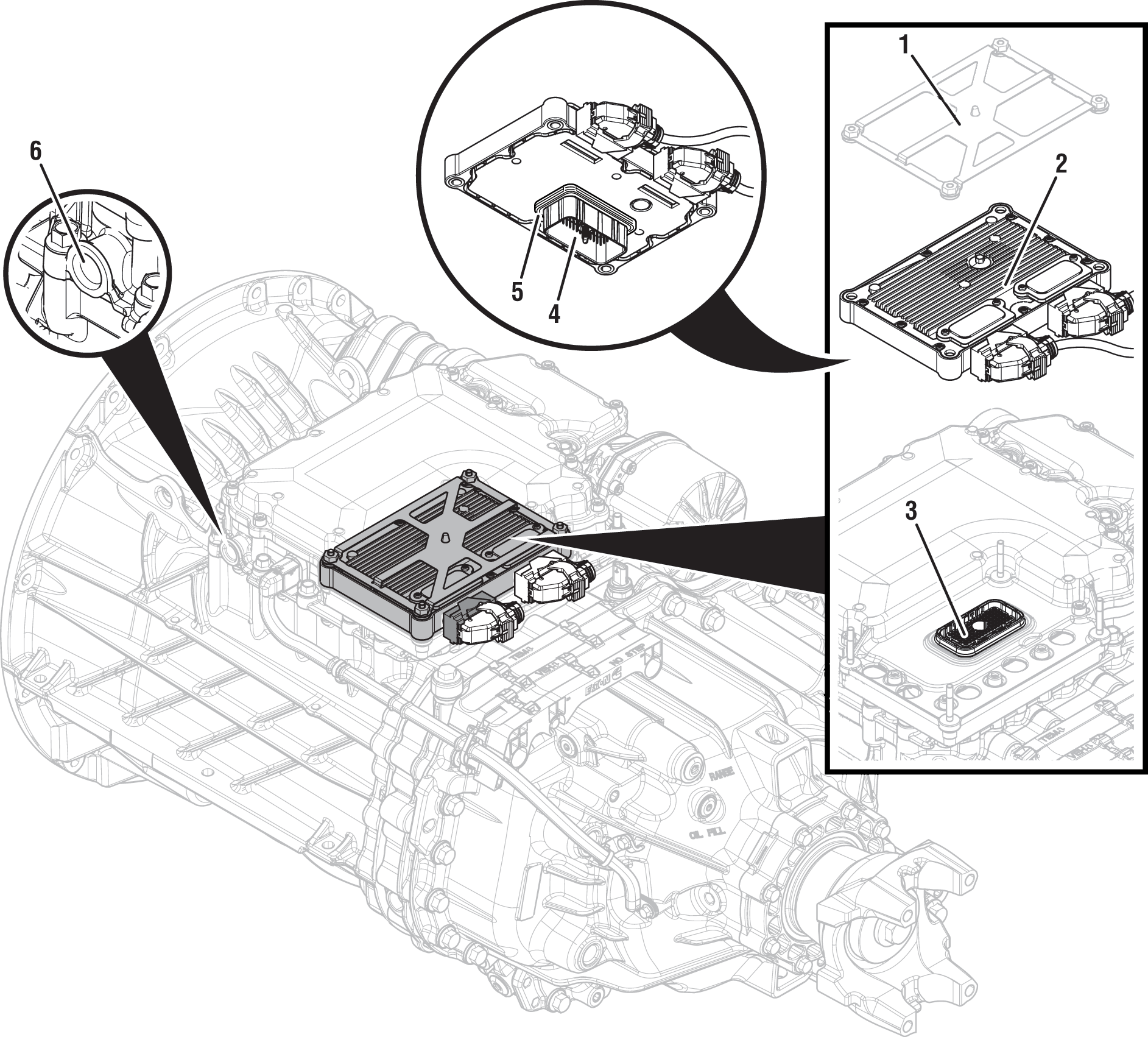
1. Transmission Control Module (TCM) Cover 2. Transmission Control Module (TCM) 3. 74-Way Transmission Harness Connector (TCM-side) 4. 74-Way Transmission Harness Connector (MTM-side) 5. Transmission Control Module (TCM) Seal 6. MTM Air Inlet Port |
Fault Code 788 Troubleshooting
Set the vehicle parking brake and chock wheels.
Record transmission fault codes, FMIs, occurrences, and timestamps from Service Activity Report created during the Diagnostic Procedure.
If Fault Code 788 is Active or Inactive, Go to Step B
Key off.
Refer to OEM guidelines and vent vehicle air supply line to MTM.
Refer to OEM guidelines and remove vehicle air supply line at MTM.
Inspect vehicle air supply line and MTM air inlet port for contamination, moisture, corrosion and/or debris.
Note: Verify MTM inlet screen is installed and free of contamination and/or debris.

If contamination is found, refer to OEM guidelines for repair or replacement of vehicle air system. Replace Mechatronic Transmission Module (MTM) and Inertia Brake Assembly. Go to Step V
Note: MTM removal and installation requires transmission be removed from vehicle. Reference Endurant XD Service Manual TRSM0960, Transmission Removal Service Procedure.
If no contamination is found, Go to Step C
Remove MTM.
Note: MTM removal and installation requires transmission be removed from vehicle. Reference Endurant XD Service Manual TRSM0960, Transmission Removal Service Procedure.
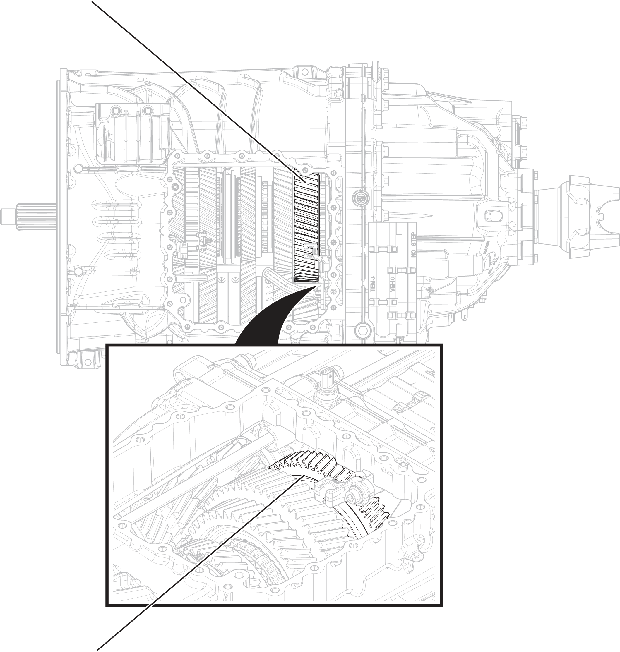
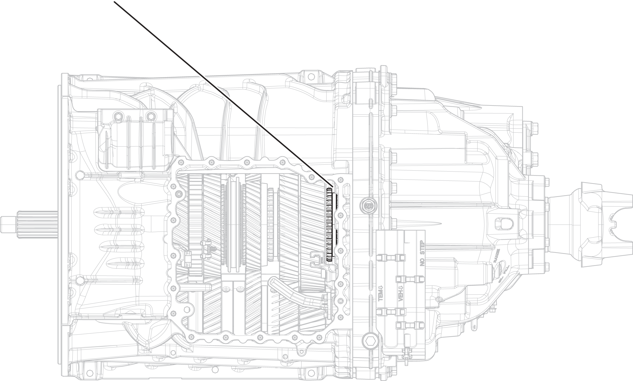
Inspect Driven Gear 1st for excessive fore and aft movement.

Inspect Reverse Gear for excessive fore and aft movement.
If excessive gear movement is evident, inspect Main Shaft Assembly for cause and repair. Go to Step V
If no excessive gear movement is evident, Go to Step D
Inspect Rail D Sliding Clutch yoke slot for wear.

Shift Rail D Sliding Clutch into neutral position (if necessary).
Shift Rail D Sliding Clutch into Driven gear 1st engagement position (fore).
Inspect Reverse Gear and Rail D Sliding Clutch clutching teeth for wear.
Return Rail D Sliding Clutch to neutral position.
Shift Rail D Sliding Clutch into Reverse Gear engagement position (aft).
Inspect Driven Gear 1st and Rail D Sliding Clutch clutching teeth for wear.
Return Rail D Sliding Clutch to neutral position.
If Rail D Sliding Clutch shifts into all three positions and no clutching teeth wear is present, replace Mechatronic Transmission Module (MTM). Go to Step V
If Rail D Sliding Clutch does not shift into all three positions or clutching teeth wear is present, replace Rail D Sliding Clutch, Driven Gear 1st, Reverse Gear and Mechatronic Transmission Module (MTM). Go to Step V
Key off.
Reconnect all connectors and verify all components are properly installed.
Key on with engine off.
Connect ServiceRanger.
Go To “Fault Codes”.
Select “Clear All Faults”.
Operate vehicle and attempt to reset the fault code or duplicate the previous complaint.
Check for fault codes using ServiceRanger.
If no fault codes set and vehicle operates properly, test complete.
If Fault Code 788 sets Active, Go to Step A
If a fault code other than 788 sets Active, troubleshoot per the Fault Code Isolation Procedure Index.