Endurant XD
TRTS0960 EN-US
|
August 2025 - A
Manually Actuate Rail A Procedure
Special Instructions
None
Special Tools
- Mechanical Diagnostic Kit (RR2011TR)
Component Identification
 |
1. MTM Cap Screws, Long (x4) - 13 mm 2. MTM Cap Screws, Special (x2) - 15 mm 3. MTM Cap Screws (x14) - 13 mm 4. Mechatronic Transmission Module (MTM) 5. Main Housing 6. Output Speed Sensor Connector |
Procedure – Manually Actuate Rail A
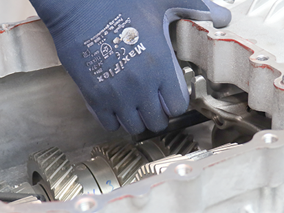
Use hand to push Rail A Yoke forward, moving Rail A Synchronizer to neutral position (if necessary).
Caution
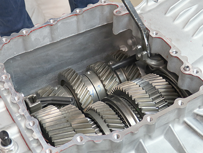
Place pry-bar between Rail A Yoke and Main Housing.
Caution
Return to troubleshooting procedure and use pry-bar to shift Rail A as required.