Endurant XD
TRTS0960 EN-US
|
August 2025 - A
Manually Actuate Rail B Procedure
Special Instructions
None
Special Tools
- Mechanical Diagnostic Kit (RR2011TR)
Component Identification
 |
1. MTM Cap Screws, Long (x4) - 13 mm 2. MTM Cap Screws, Special (x2) - 15 mm 3. MTM Cap Screws (x14) - 13 mm 4. Mechatronic Transmission Module (MTM) 5. Main Housing 6. Output Speed Sensor Connector |
Procedure – Manually Actuate Rail B
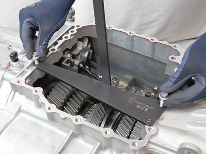
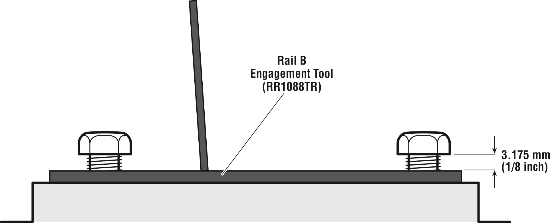
Install the Rail B Engagement Tool (RR1088TR) to the Main Housing
Install and hand tighten 2 MTM cap screws leaving a 3.175 mm (1/8 inch) gap between the cap screws and tool base.
Notice

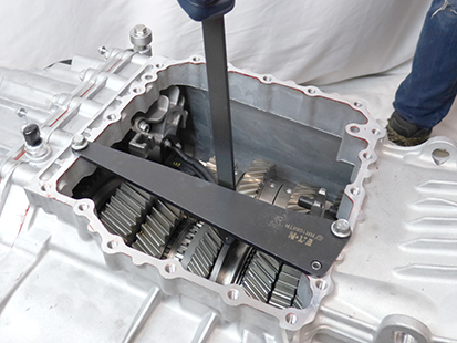
Shift Rail B Synchronizer Sliding Sleeve into the Fore position.
CautionNotice
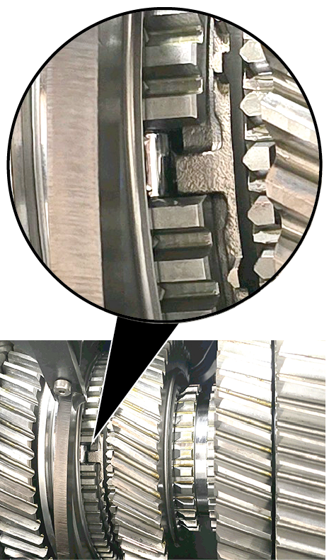
Inspect the Rail B Synchronizer for three synchronizer rollers. Rotate the Input Shaft to view the three rollers.
- If all three synchronizer rollers are present, return to the troubleshooting procedure.
- If one or more synchronizer rollers are not present, contact Eaton Cummins Automated Transmission Technologies for further diagnostic instructions. For Help Line phone numbers, go to Contact Information.
