Wiring Inspection and Troubleshooting Procedure
Overview
This is a set of recommendations for how to troubleshoot potential wiring issues in the vehicle. These issues may be resident in the OEM supplied Vehicle Harness, Body Harness, or other ancillary wiring, depending on the fault code or condition that is taking place. When troubleshooting wiring, consider that wiring failures can be continuous, intermittent or there may be no failure of the wiring at all.
Possible Causes
- Vehicle Harness
- Wiring shorted to power, shorted to ground or open
- Terminals bent, spread, corroded, or loose
- Missing or failed connector seals
- Wiring damaged, pinched or rubbed through
Visual Inspection
- Make sure all connectors are clean and tight.
- Inspect the length of the wiring between connections and check for signs of pinched or chafed wiring.
- Inspect connectors for debris and contamination. Only clean if necessary.
- When taking a volt/ohm meter reading at a connector, inspect for loose terminals, corrosion and bent or spread pins.
Note: If damage is found to OEM wiring, refer to OEM guidelines for repair or replacement of wiring and connectors.
- When reconnecting, the use of NyoGel 760G on electrical contacts is recommended. Ensure all connectors are clean and tight.
Recommendations for Using a Volt/Ohm Meter
- Use a quality digital auto-ranging volt/ohm meter.
- When using a volt/ohm meter without auto-ranging capabilities, use the correct range setting for the reading.
- Verify that the battery and fuse are in good working order.
- Some volt/ohm meters have multiple sockets for test leads. Use the correct socket for the type of reading you need.
- Reset the volt/ohm meter to zero before testing by holding the leads together and verifying that the scale shows zero ohms.
- Use the correct pin test adapter for the connector(s) that are being tested. Incorrect test lead sizes may cause permanent damage to connector pins.
- When measuring resistance, be sure that the ignition is off and the circuit is completely unpowered.
Example Voltage Readings
Voltage Reading
Verify the voltage measurement is within range. Low voltage readings may be a sign of poor voltage supply or excessive in-line resistance. Pay close attention to whether the reading requires a key-on or key-off condition.
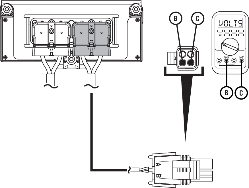
| Pins | Range | Reading(s) |
|---|---|---|
| B to C | Within 0.6 V of Battery Voltage | 12.5 V |
Example Circuit Continuity Readings
Circuit has Continuity
The circuit is complete when the resistance reading is within range. A circuit reading infinite resistance or Open Lead (OL) does not have continuity.
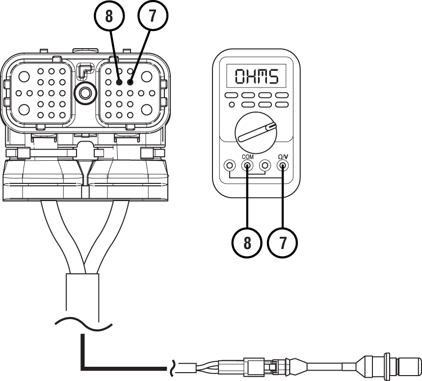
| Pins | Range | Reading(s) |
|---|---|---|
| 7 to 8 | 2.0k – 4.5k ohms | 3.2k ohms |
Open Circuit
The circuit is incomplete when the resistance reading is infinite or Open Lead (OL). In cases where resistance readings are greater than 10k ohms, the circuit has some continuity, but is not making good contact. These can generally be treated as an open circuit.
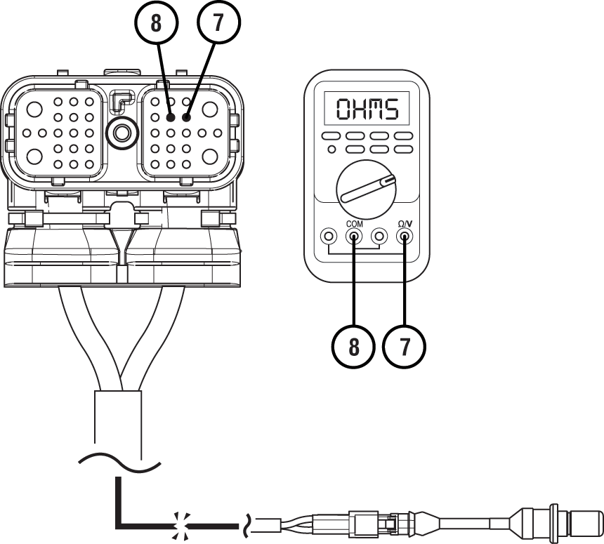
| Pins | Range | Reading(s) |
|---|---|---|
| 7 to 8 | 2.0k – 4.5k ohms | OL |
Example End to End Resistance
End to End Resistance is Within Range
The wire has continuity when the resistance reading is within range. A wire reading infinite resistance or Open Lead (OL) does not have continuity.
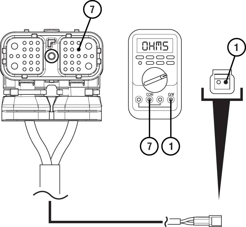
| Pins | Range | Reading(s) |
|---|---|---|
| 7 to 1 | 0.0 – 0.3 ohms | 0.2 ohms |
End to End Resistance is Too High
When the resistance is higher than the acceptable range there is additional resistance in this wire. Check for corrosion, loose or spread pins or damage to the harness.

| Pins | Range | Reading(s) |
|---|---|---|
| 7 to 1 | 0.0 – 0.3 ohms | 2.0 ohms |
Open Circuit
The circuit is incomplete when the resistance reading is infinite or Open Lead (OL). Check for wire abrasions, cuts, loose or spread pins and unseated connectors.
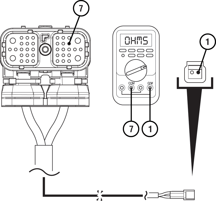
| Pins | Range | Reading(s) |
|---|---|---|
| 7 to 1 | 0.0 – 0.3 ohms | OL |
Short Circuit to Chassis Ground
Short to Ground
A wire is shorted to ground when the resistance between a non-ground wire and chassis ground shows continuity. Low resistance values (near 0 ohms) indicate a direct short to ground. Higher resistance values may indicate a partial-short.
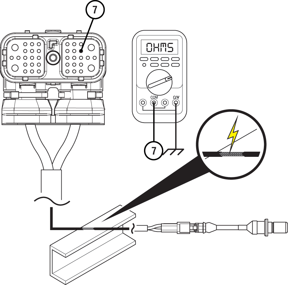
| Pins | Range | Reading(s) |
|---|---|---|
| 7 to Ground | Open Circuit (OL) | 2.0 ohms |
No Short to Ground
The wire is not shorted to ground when the resistance between a non-ground wire and chassis ground is infinite or Open Lead (OL). This wire has no continuity to chassis ground.
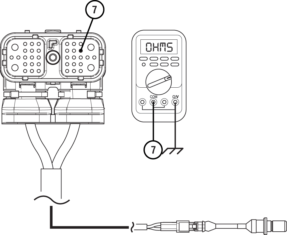
| Pins | Range | Reading(s) |
|---|---|---|
| 7 to Ground | Open Circuit (OL) | OL |
Short to Another Circuit
Two Circuits Shorted Together
When wires from two unrelated circuits show continuity (low resistance) to one another, these circuits are shorted together.
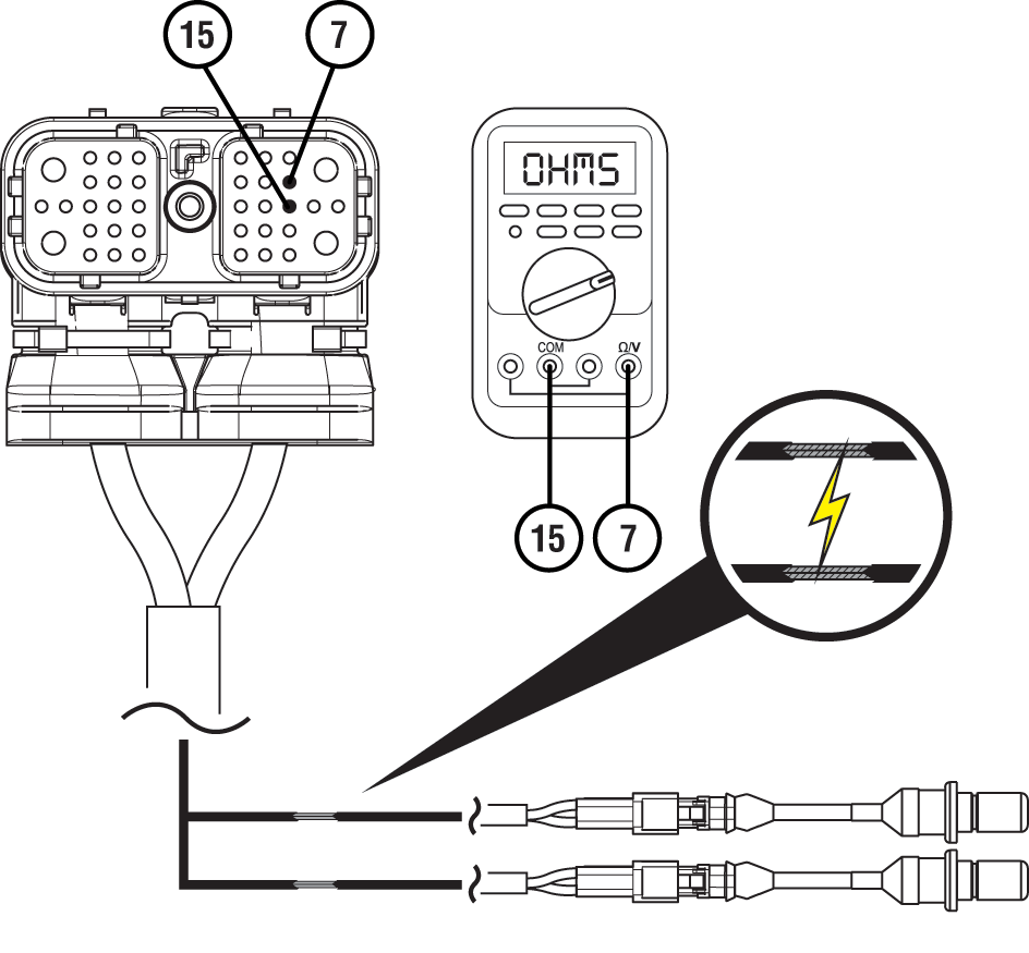
| Pins | Range | Reading(s) |
|---|---|---|
| 7 to 15 | Open Circuit (OL) | 2.0 ohms |
Two Circuits Not Shorted Together
When wires from the two unrelated circuits show an infinite resistance or Open Lead (OL) between one another, these wires are not shorted together.
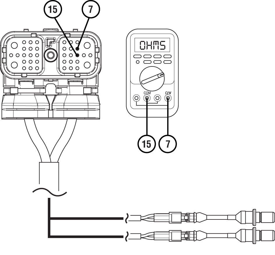
| Pins | Range | Reading(s) |
|---|---|---|
| 7 to 15 | Open Circuit (OL) | OL |