Electrical Pretest Gen2 ECA
Overview
This procedure provides a basic test of the vehicle electrical system. A well-functioning electrical supply is required for proper operation of the UltraShift PLUS transmission.
This test verifies the vehicle batteries are fully charged, proper battery and ignition voltage are being supplied to the transmission components, and the electrical system can supply proper voltage and current when under load.
Fault codes that set for a specific transmission give additional information about performance issues detected on that vehicle. If a unit has an Active fault code, or repeated occurrences of an Inactive fault code, refer to the troubleshooting procedure for that fault code. Certain fault code troubleshooting procedures require completion of the Troubleshooting Pretest. Some electrical system failures may cause performance problems without setting a fault code.
Detection
None
Conditions to Set Fault Code Active
None
Fallback
None
Conditions to Set Fault Code Inactive
None
Possible Causes
- Vehicle Batteries
- Internal failure
- Vehicle Charging System
- Charging system failed
- Alternator-Generator failed
- Vehicle Harness
- Poor power or ground supply to Transmission Electronic Control Unit (TECU)
- Bent, spread, corroded or loose terminals
- Wiring shorted to ground, shorted to power or open
- Improperly seated or missing 30-amp fuse
- Vehicle Power and Ground Supply to ECA
- Poor power or ground supply to ECA
- Wiring shorted to ground, shorted to power or open
- Improperly seated or missing 40-amp fuse
- Bent, spread, corroded or loose terminals
- Transmission Harness
- Wiring shorted to ground, shorted to power or open
- Bent, spread, corroded or loose terminals
Additional Tools
Battery load testing equipment (see OEM for specific recommendations)
Component Identification
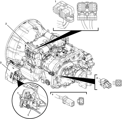 |
1. 38-Way Vehicle Harness Connector 2. Transmission Electronic Control Unit (TECU) 3. ECA Shield 4. 4-Way Diagnostic Connector 5. Electronic Clutch Actuator (ECA) 6. 2-Way ECA Connector |
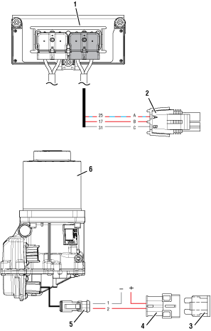 |
1. Transmission Electronic Control Unit (TECU) 2. 4-Way Diagnostic Connector 3. 40-amp Fuse 4. In-line Fuse Holder 5. 2-Way ECA Connector 6. Electronic Clutch Actuator (ECA) |
 |
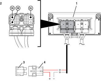 |
1. Transmission Electronic Control Unit (TECU) 2. 38-Way Vehicle Harness Connector 3. 30-amp Fuse 4. In-line Fuse Holder |
 |
Electrical Pretest Gen2 ECA
Key off.
Measure voltage across all batteries. Record reading(s) in table.
Inspect starter, battery terminals and transmission 30-amp in-line fuse holder connections for damage and bent, spread, corroded or loose terminals.
Visually inspect Vehicle Harness between the power supply and the TECU for signs of rubbing or chafing to the wiring.
Note: Some chassis use a power and ground distribution block separate from the battery or may route power and ground to the starter. Be sure to clean and inspect connections at this location and at the battery.
If damage is found, repair or replace wiring per OEM guidelines, Go to Step B
If no damage is found, Go to Step B
| Battery Voltage |
|---|
Key off.
Inspect the ECA 40-amp In-line Fuse Holder Connections for damage and bent, spread, corroded or loose terminals.
Visually inspect ECA Power Supply Harness between the power supply and the ECA for signs of rubbing or chafing to the wiring.
Note: Some chassis use a power and ground distribution block separate from the battery or may route power and ground to the starter. Be sure to clean and inspect connections at this location and at the battery.

If damage is found, repair or replace wiring per OEM guidelines. Repeat test.
If no damage is found, Go to Step C
Key off.
NoticeLoad test each vehicle battery per OEM specifications. Record reading(s).
If all batteries pass the Load Test, Go to Step D
If any battery does not pass the Load Test, refer to OEM guidelines for repair or replacement of batteries. D
| Battery | Voltage Drop | Load Test Status (Pass/Fail) |
|---|---|---|
| 1 | ||
| 2 | ||
| 3 | ||
| 4 | ||
| 5 |
Reconnect all harnesses and connectors.
Key on with engine off.
Remove connector cover of 4-Way Diagnostic Connector on the Transmission Harness.
Measure voltage between Pin B (Service Battery positive) and Pin C (Service Battery negative). Record reading(s).
Warning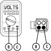
Compare reading(s) in table.
If readings are in range, Go to Step G
If readings are out of range, Go to Step E
| Pins | Range | Reading(s) |
|---|---|---|
| B to C | Within 1.2 V of Battery Voltage |
Key off.
Disconnect 38-Way Vehicle Harness Connector from TECU.
Inspect connector body for damage and bent, spread, corroded or loose terminals.
Measure voltage between 38-Way Connector Pin 38 (Battery positive) and Pin 36 (Battery negative). Record reading(s).
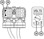
Compare reading(s) in table.
If readings are in range, Go to Step F
If readings are out of range, refer to OEM guidelines for repair or replacement of battery power and ground supply to TECU. Repeat Electrical Pretest.
| Pins | Range | Reading(s) |
|---|---|---|
| 38 to 36 | Within 1.2 V of Battery Voltage |
Key off.
Disconnect 38-Way Transmission Harness Connector from TECU.
Inspect connector body for damage and bent, spread, corroded or loose terminals.
Measure resistance between Pin 31 and Pin C. Record reading(s) in table.
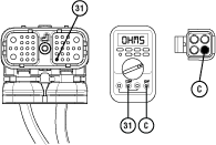
Measure resistance between Pin 17 and Pin B. Record reading(s) in table.
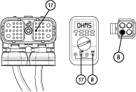
Measure resistance between Pin B and ground. Record reading(s) in table.

Compare reading(s) in table.
If readings are out of range, replace Transmission Harness. Repeat Electrical Pretest.
If readings are in range, replace TECU. Repeat Electrical Pretest.
| Pins | Range | Reading(s) |
|---|---|---|
| 31 to C | 0.0–0.3 Ohms | |
| 17 to B | 0.0–0.3 Ohms | |
| B to Ground | Open Circuit (OL) |
Key off.
Reconnect all harnesses and connectors.
Key on with engine off.
Remove connector cover of 4-Way Diagnostic Connector on the Transmission Harness.
Measure voltage between Pin A (Service Ignition positive) and Pin C (Service Battery negative). Record reading(s).
Warning
Compare reading(s) in table.
If readings are in range, Go to Step J
If readings are out of range, Go to Step H
| Pins | Range | Reading(s) |
|---|---|---|
| A to C | Within 1.2 V of Battery Voltage |
Key off.
Disconnect 38-Way Vehicle Harness Connector from TECU.
Verify connector is free from any corrosion; the terminals are not bent, spread or loose; and there is no damage to the connector body.
Key on with engine off.
Measure voltage between 38-Way Connector Pin 35 (Ignition positive) and Pin 36 (Battery negative). Record reading(s) in table.
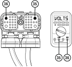
Compare reading(s) in table.
If readings are in range, Go to Step I
If readings are out of range, refer to OEM guidelines for repair of ignition voltage supply. Repeat Electrical Pretest.
| Pins | Range | Reading(s) |
|---|---|---|
| 35 to 36 | Within 1.2 V of Battery Voltage |
Key off.
Disconnect 38-Way Transmission Harness Connector from TECU.
Inspect connector body for damage and bent, spread, corroded or loose terminals.
Measure resistance between Pin 25 and Pin A. Record reading(s) in table.
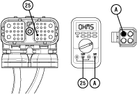
Measure resistance between Pin A and ground. Record reading(s) in table.

Compare reading(s) in table.
If readings are out of range, replace Transmission Harness. Repeat Electrical Pretest.
If readings are in range, replace TECU. Repeat Electrical Pretest.
| Pins | Range | Reading(s) |
|---|---|---|
| 25 to A | 0.0–0.3 Ohms | |
| A to Ground | Open Circuit (OL) |
Key off.
Disconnect 2-Way ECA Connector.
Verify connector is free from any corrosion; the terminals are not bent, spread or loose; and there is no damage to the connector body.

If damage is found to the ECA Power Harness, refer to OEM guidelines for repair or replacement of the ECA Power Harness. Repeat Electrical Pretest.
If damage to the ECA is found, replace ECA. Repeat Electrical Pretest.
If no damage is found, Go to Step K
Key off.
Measure voltage between 2-Way ECA Connector Pin 2 (Battery positive) and Pin 1 (Battery negative). Record reading(s) in table.
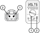
Compare reading(s) in table.
If readings are in range, no issue is found, Go to Step L
If readings are out of range, refer to OEM guidelines for repair or replacement of the ECA Power Harness. Repeat Electrical Pretest.
| Pins | Range | Reading(s) |
|---|---|---|
| 1 to 2 | Within 1.2 V of Battery Positive (+) |
Key off.
Measure voltage between 2-Way ECA Connector Pin 2 (Battery positive) and ground. Record reading(s) in table.
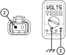
Compare reading(s) in table.
If readings are in range, Electrical Pretest Complete.
If readings are out of range, the Battery positive and Battery negative wires are incorrectly pinned in the ECA 2-Way Connector. Refer to OEM requirements for repair or replacement of the ECA Power Harness. Repeat Electrical Pretest.
| Pins | Range | Reading(s) |
|---|---|---|
| 2 to Ground | Within 1.2 V of Battery Positive (+) |