Fault Code 13: J1939 Shift Control Device
J1587: MID 130 SID 231 FMI 8, 11
J1939: SA 3 SPN 751 FMI 8, 11
Overview
The UltraShift PLUS transmission may be equipped with a J1939 Shift Control Device. This version of the Shift Control Device uses the J1939 Data Link to broadcast the driver’s shift request to the Transmission Electronic Control Unit (TECU). The system includes redundant neutral request and neutral confirmation signals hard-wired between the Shift Control Device and TECU. These redundant signals allow the transmission to achieve neutral if the J1939 Data Link fails.
Fault Code 13 indicates that either the TECU lost J1939 Data Link communications with the Shift Control Device or that the neutral request status received over J1939 and the neutral request status received through the hard-wired signal do not match.
Detection
The ignition key is on and the TECU has not detected any low battery system faults.
Conditions to Set Fault Code Active
FMI 8 – Abnormal Frequency: TECU compares the J1939 Data Link message from the Shift Control Device to the hard-wired neutral signal request. When 10 consecutive messages do not match, the fault code sets Active.
FMI 11 – FMI Unknown: TECU has lost communication with the J1939 Shift Control Device but can communicate with other devices on the J1939 Data Link. When no J1939 messages have been received for 5 seconds, the fault code sets Active.
Fallback
FMI 8
- “F” flashes in gear display.
- Service light flashes (if equipped).
- Engine may not crank.
- Transmission may not engage a gear from neutral.
FMI 11
- “F” does not flash in gear display.
- Service light does not flash (if equipped).
- Transmission may not attempt to shift.
- Until the fault becomes Inactive, driver may have to shut off engine with transmission in gear.
Conditions to Set Fault Code Inactive
All FMIs: TECU receives a valid message over the J1939 Data Link.
Possible Causes
FMI 8
- Vehicle Harness
- Bent, spread or loose terminals
- Wiring shorted to ground, shorted to power or open
- Shift Control Device
- Internal failure
- TECU Configuration Setting
FMI 11
- Data Link
- Bent, spread, or loose terminals
- Wiring shorted to ground, shorted to power or open
- Vehicle Harness
- Bent, spread or loose terminals
- Shift Control Device Power Supply
- Loss of supply battery voltage
- Loss of supply ignition voltage
- Loss of supply ground connection
- Shift Control Device
- Internal failure
Component Identification
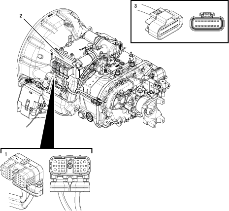 |
1. 38-Way Vehicle Harness Connector 2. Transmission Electronic Control Unit (TECU) 3. OEM J1939 Shift Control Connector (in cab) |
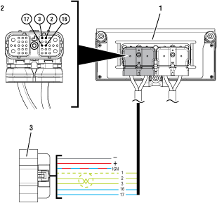 |
1. Transmission Electronic Control Unit (TECU) 2. 38-Way Vehicle Harness Connector 3. OEM J1939 Shift Control Connector |
 |
Fault Code 13 Troubleshooting
Set vehicle parking brake and chock wheels.
Record the transmission fault codes, FMIs, occurrences, and timestamps from the Service Activity Report created during the Diagnostic Procedure.
If vehicle J1939 Data Link fault codes are set, refer to OEM guidelines for repair or replacement of the vehicle J1939 Data link. Go to Step V
If transmission Fault Code 35 is set, troubleshoot per Fault Code Isolation Procedure Index.
If vehicle J1939 Data Link fault codes and Fault Code 35 are NOT set, Go to Step B
Record FMI set for Fault Code 13 and vehicle OEM in table.
If Fault Code 13 FMI 8 is Active or Inactive and the vehicle OEM is Freightliner, Go to Step M
If Fault Code 13 FMI 8 is Active or Inactive and the vehicle OEM is NOT Freightliner, Go to Step J
If Fault Code 13 FMI 11 is Active (All OEMs), Go to Step D
If Fault Code 13 FMI 11 is Inactive (All OEMs), Go to Step C
| FMI | OEM |
|---|---|
Set parking brake and chock wheels.
Place transmission in PD Mode. See more about Product Diagnostic (PD) Mode.
Note: Transmission does not enter PD Mode when Active fault codes exist.

Wiggle J1939 Data Link Wiring. Look for signs of rubbing, chafing or corrosion on the wires.
Wiggle the power and ground supply to the Shift Control Device. Look for signs of rubbing, chafing or corrosion on the wires.
Exit PD Mode by powering down.
Notice
If any fault code became Active while wiggling the power or ground supply to the Shift Control Device, refer to OEM guidelines for repair or replacement of the power and ground supply to the Shift Control Device. Go to Step V
If any fault code became Active while wiggling J1939 Data Link Wiring refer to OEM guidelines for repair or replacement of J1939 Data Link. Go to Step V
If no fault codes became Active while wiggling either harness, Go to Step D
Key off.
Note: See OEM wiring diagram and connector views to identify the corresponding pin at the Shift Control Device Connector.
Disconnect OEM J1939 Shift Control Connector.
Inspect OEM J1939 Shift Control Connector body for damage and bent, spread, corroded or loose terminals.
Key on with engine off.
Measure voltage between Battery Positive (+) Pin on OEM J1939 Shift Control Connector and ground. Record reading(s) in table.
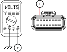
Compare reading(s) in the table.
If readings are in range, Go to Step E
If readings are out of range, refer to OEM guidelines for repair or replacement of wiring between the Shift Control Device Connector and Battery Positive (+). Go to Step V
| Pins | Range | Reading(s) |
|---|---|---|
| Battery Positive (+) at OEM J1939 Shift Control Connector to Ground | Within 1.2 V of battery voltage |
Key on with engine off.
Note: See OEM wiring diagram and connector views to identify the corresponding pin at the Shift Control Device Connector.
Measure voltage between Ignition Pin on OEM J1939 Shift Control Connector and ground.
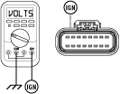
If readings are in range, Go to Step F
If readings are out of range, refer to OEM guidelines for repair or replacement of ignition wiring to the Shift Control Device. Go to Step V
| Pins | Range | Reading(s) |
|---|---|---|
| Switched Ignition at OEM J1939 Shift Control Connector to Ground | Within 1.2 V of battery voltage |
Key on with engine off.
Note: See OEM wiring diagram and connector views to identify the corresponding pin at the OEM J1939 Shift Control Connector.
Measure resistance from Ground Supply Pin on OEM J1939 Shift Control Connector to ground. Record reading(s) in table.
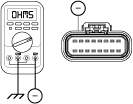
Compare reading(s) in table.
If readings are in range, Go to Step G
If readings are out of range, refer to OEM guidelines for repair or replacement of wiring between Ground Supply Pin on OEM J1939 Shift Control Connector and vehicle ground. Go to Step V
| Pins | Range | Reading(s) |
|---|---|---|
| Ground Supply at OEM J1939 Shift Control Connector Pin to Ground | 0.0–0.3 ohms |
Key off.
Note: See OEM wiring diagram and connector views to identify the corresponding pin at the OEM J1939 Shift Control Connector.
Disconnect 38-Way Vehicle Harness Connector from TECU.
Inspect 38-Way Connector body for damage and bent, spread, corroded or loose terminals.
Measure resistance between 38-Way Vehicle Harness Connector Pin 2 and the corresponding J1939 Negative (-) Pin on the OEM J1939 Shift Control Connector. Record reading(s) in table.
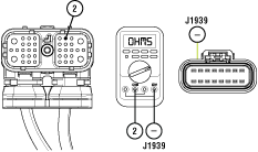
Measure resistance between 38-Way Vehicle Harness Connector Pin 2 and ground. Record reading(s) in table.
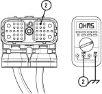
Compare reading(s) in table.
If readings are in range, Go to Step H
If readings are out of range, refer to OEM guidelines for repair or replacement of J1939 Data Link wiring between TECU and the Shift Control Device. Go to Step V
| Pins | Range | Reading(s) |
|---|---|---|
| 2 to J1939 Negative (-) Shift OEM J1939 Shift Control Connector Pin | 0.0–0.6 ohms | |
| 2 to Ground | Open Circuit (OL) |
Key off.
Note: See OEM wiring diagram and connector views to identify the corresponding pin at the OEM J1939 Shift Control Connector.
Measure resistance between 38-Way Vehicle Harness Connector Pin 3 and the corresponding J1939 Positive (+) Pin on the OEM J1939 Shift Control Connector. Record reading(s) in table.
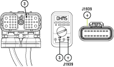
Measure resistance between 38-Way Vehicle Harness Connector Pin 3 and ground. Record reading(s) in table.
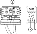
Compare reading(s) in table.
If readings are in range, Go to Step I
If readings are out of range, refer to OEM guidelines for repair or replacement of J1939 Data Link Wiring between TECU and Shift Control Device. Go to Step V
| Pins | Range | Reading(s) |
|---|---|---|
| 3 to J1939 Positive (+) OEM J1939 Shift Control Connector | 0.0–0.6 ohms | |
| 3 to Ground | Open Circuit (OL) |
Key off.
NoticeReconnect OEM J1939 Shift Control Connector.
Measure resistance between 38-Way Vehicle Harness Connector Pin 2 and Pin 3. Record reading(s) in table.
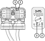
Compare reading(s) in table.
If readings are in range, refer to OEM guidelines for repair or replacement of Shift Control Device. Go to Step V
If readings are out of range, refer to OEM guidelines for repair or replacement of J1939 Data Link. Go to Step V
| Pins | Range | Reading(s) |
|---|---|---|
| 2 to 3 | 50–70 ohms |
Key off.
Note: See OEM wiring diagram and connector views to identify the corresponding pin at the OEM J1939 Shift Control Connector.
Disconnect OEM J1939 Shift Control Connector.
Inspect Connector body for damage and bent, spread, corroded or loose terminals
Measure resistance between 38-Way Vehicle Harness Connector Pin 16 and corresponding neutral request signal pin on the OEM J1939 Shift Control Connector. Record reading(s) in table.
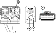
Measure resistance between 38-Way Vehicle Harness Connector Pin 16 and ground. Record reading(s) in table.
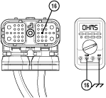
Compare reading(s) in table.
If readings are in range, Go to Step K
If readings are out of range, refer to OEM guidelines for repair or replacement of wiring between 38-Way Vehicle Harness Connector Pin 16 and corresponding pin at the OEM J1939 Shift Control Connector. Go to Step V
| Pins | Range | Reading(s) |
|---|---|---|
| 16 to OEM J1939 Shift Control Connector Neutral Request Signal | 0.0–0.6 ohms | |
| 16 to Ground | Open Circuit (OL) |
Key off.
Note: See OEM wiring diagram and connector views to identify the corresponding pin at the OEM J1939 Shift Control Connector.
Measure resistance between 38-Way Vehicle Harness Connector Pin 17 and corresponding neutral request return pin at the OEM J1939 Shift Control Connector. Record reading(s) in table.
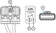
Measure resistance between 38-Way Vehicle Harness Connector Pin 17 and ground. Record reading(s) in table.
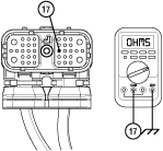
Compare reading(s) in table.
If readings are in range, Go to Step L
If readings are out of range, refer to OEM guidelines for repair or replacement of wiring between 38-Way Vehicle Harness Connector Pin 17 and corresponding pin at the OEM J1939 Shift Control Connector. Go to Step V
| Pins | Range | Reading(s) |
|---|---|---|
| 17 to OEM J1939 Shift Control Connector Neutral Request Return Pin | 0–0.6 ohms | |
| 17 to Ground | Open Circuit (OL) |
Key off.
Reconnect all electrical connections.
Key on with engine off.
Connect ServiceRanger.
Retrieve and record the transmission fault codes and FMIs, and their occurrences and timestamps.
If Fault Code 13 FMI 8 is Active, repair or replace Shift Control Device per OEM guidelines. Go to Step V
If Fault Code 13 FMI 8 is Inactive, refer to OEM guidelines for repair or replacement of wiring between 38-way Vehicle Harness Connector Pin 16 and corresponding pin at the OEM J1939 Shift Control Connector. Also repair or replace wiring between 38-Way Vehicle Harness Connector Pin 17 and corresponding pin at the OEM J1939 Shift Control Connector. Go to Step V
Record the vehicle transmission driver interface device type in table.
If Fault Code 13 FMI 8 is Active or Inactive and the vehicle is equipped with an Eaton Push Button, Go to Step J
If Fault Code 13 FMI 8 is Active and the vehicle is equipped with a Freightliner shift stalk, Go to Step N
If Fault Code 13 FMI 8 is Inactive and the vehicle is equipped with a Freightliner shift stalk, TECU is properly configured. Go to Step V
| Transmission Driver Interface Device Type |
|---|
Key on.
Connect ServiceRanger.
Go To “Configuration”.
Select “Options”.
From the “Regional Calibration” configuration “New Value” drop down select “DTNA 2017 Cascadia 5573603”.
Select “Apply” and follow on-screen prompts.
Key off.
Reconnect all connectors and verify that all components are properly installed.
Key on with engine off.
Clear fault codes using ServiceRanger.
Drive vehicle and attempt to reset the code or duplicate the previous complaint.
Check for fault codes using ServiceRanger.
If no fault codes set and vehicle operates properly, test complete.
If Fault Code 13 sets Active during the test drive, Go to Step A
If a fault code other than 13 sets, troubleshoot per Fault Code Isolation Procedure Index.