J1587 Data Link
Overview
This symptom-driven test is performed if there is a failure of the J1587 Data Link on the vehicle. Most UltraShift PLUS transmission functions use J1939 as the primary communication method and utilize J1587 as a redundant or backup communication method. Therefore, a loss of J1587 Data Link may not have a significant affect on the transmission system.
Detection
- ServiceRanger or other diagnostic tools has limited functionality.
- Other vehicle ECUs may set J1587 fault codes.
Possible Causes
- J1587 Data Link
- Damage between TECU and 9-Way Diagnostic Connector
- Bent, spread, corroded or loose terminals
- Wiring shorted to ground, shorted to power or open
Component Identification
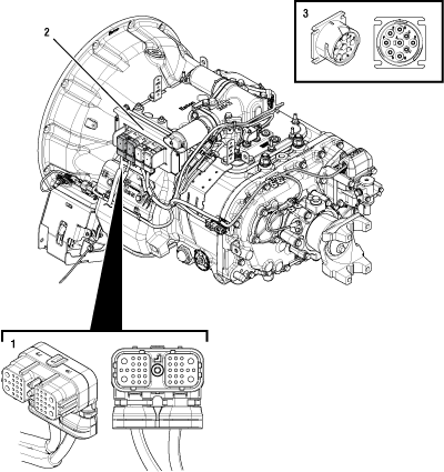 |
1. 38-Way Vehicle Harness Connector 2. Transmission Electronic Control Unit (TECU) 3. 9-Way Diagnostic Connector (in cab) |
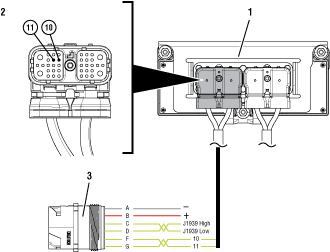 |
1. Transmission Electronic Control Unit (TECU) 2. 38-Way Vehicle Harness Connector 3. 9-Way Diagnostic Connector (in cab) |
 |
J1587 Data Link Test
Key off.
NoticeMeasure voltage between 9-Way Diagnostic Connector Pin B and Pin A.
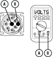
Compare reading(s) in table.
If readings are in range, Go to Step B
If readings are out of range, repair battery or ground wire to vehicle diagnostic connector. Go to Step V
| Pins | Range | Reading |
|---|---|---|
| B to A | Within 0.6 V of Battery Voltage |
Key off.
Disconnect 38-Way Vehicle Harness Connector from TECU.
Measure resistance between 9-Way Diagnostic Connector Pin F and 38-Way Vehicle Harness Connector Pin 10.
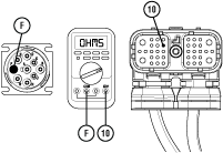
Compare reading(s) in table.
If readings are in range, Go to Step C
If readings are out of range, refer to OEM guidelines for repair or replacement of J1587 Data Link. Go to Step V
| Pins | Range | Reading |
|---|---|---|
| 10 to F | 0–0.3 ohms |
Measure resistance between 9-Way Diagnostic Connector Pin F and ground. Record reading(s) in table.
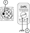
Compare reading(s) in table.
If readings are in range, Go to Step D
If readings are out of range, refer to OEM guidelines for repair or replacement of J1587 Data Link. Go to Step V
| Pins | Range | Reading |
|---|---|---|
| F to Ground | Open Circuit (OL) |
Measure resistance between 9-Way Diagnostic Connector Pin G and 38-Way Vehicle Harness Connector Pin 11. Record reading(s) in table.
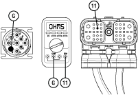
Compare reading(s) in table.
If readings are in range, Go to Step E
If reading are out of range, refer to OEM guidelines for repair or replacement of J1587 Data Link. Go to Step V
| Pins | Range | Reading |
|---|---|---|
| 11 to G | 0–0.3 ohms |
Measure resistance between either 9-Way Diagnostic Connector Pin G and ground.
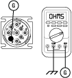
Compare reading(s) in table.
If readings are in range, no problem identified. Go to Step V
If readings are out of range, refer to OEM guidelines for repair or replacement of J1587 Data Link. Go to Step V
| Pins | Range | Reading |
|---|---|---|
| G to Ground | Open Circuit (OL) |
Key on with engine off.
Connect ServiceRanger.
Note: If ServiceRanger does not communicate with the transmission and other vehicle devices, verify proper ServiceRanger communication adapter settings before continuing. For more information, see the ServiceRanger User’s Guide TCMT0072.
Attempt to communicate with vehicle components.
If ServiceRanger communicates with other vehicle devices, test complete.
If ServiceRanger does not communicate with other devices, Go to Step A