Transmission Shift Complaint
Overview
This symptom-driven test is performed if a shift complaint exists and there are no Active or Inactive fault codes.
Detection
- Transmission may not be able to complete a shift.
- Transmission may exhibit slow or harsh shifting.
Possible Causes
- Low Capacity Inertia Brake (LCIB)
- Internal Failure
- Input Shaft Speed Sensor
- Internal Failure
- Transmission Electronic Control Unit (TECU)
- Internal Failure
- Transmission Harness
- Bent, spread, corroded or loose terminals
- Wiring shorted to ground, shorted to power or open
- Vehicle Air System
- Low vehicle air pressure
- Contamination in air supply
- Air leaks
- Filter-Regulator Failure
- Range Solenoid Valve
- Mechanical Failure
- Splitter Solenoid Valve
- Mechanical Failure
- Mechanical Transmission
- Failed Auxiliary Transmission components
- Tone Wheel damage
- Range Synchronizer Failure
- Range Cylinder, Piston or Yoke wear or damage
- Range Cover Gasket Failure
- Splitter Cylinder, Piston or Yoke wear or damage
- Splitter Cover Gasket Failure
Component Identification
 |
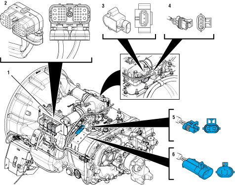
1. Transmission Electronic Control Unit (TECU) 2. 38-Way Transmission Harness Connector 3. Gear Position Sensor 4. 3-Way Gear Position Sensor Connector 5. 2-Way Gear Motor Connector (blue) 6. 2-Way Gear Motor Connector Body (blue) |
 |
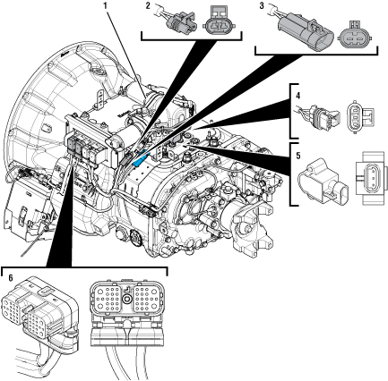
1. X-Y Shifter 2. 2-Way Rail Motor Connector (black) 3. 2-Way Rail Motor Connector Body (black) 4. 3-Way Rail Position Sensor Connector 5. Rail Position Sensor 6. 38-Way Vehicle Harness Connector |
Transmission Shift Complaint Test
Key on with engine off.
Connect ServiceRanger.
Retrieve Snapshot and VPA data by creating a Service Activity Report within ServiceRanger.
Update transmission software to latest available level.
NoticeRetrieve transmission and vehicle fault codes and FMIs, and their occurrences and timestamps.
If any Engine, ABS or other Vehicle ECU fault codes are set, troubleshoot per OEM requirements.
If any transmission fault codes set Active, troubleshoot per Fault Code Isolation Procedure Index.
If no fault codes set Active, Go to Step B
Perform the Electrical Pretest. Reference the Electronic Clutch Actuator (ECA) Identification Overview. Record the reading(s) from the Load Test in Step C of the Electrical Pretest in the table.
If Electrical Pretest passes, Go to Step C
If Electrical Pretest fails, repair per Electrical Pretest instructions. Retest vehicle operation.
| Battery | Voltage Drop | Load Test Status (Pass/Fail) |
|---|---|---|
| 1 | ||
| 2 | ||
| 3 | ||
| 4 | ||
| 5 |
Document the vehicle shift complaint by completing the Driver Questionnaire.
Drive or operate vehicle and attempt to duplicate the shift complaint.
NoticeIf the shift complaint is duplicated, while driving capture a driver triggered snapshot of the event by placing the transmission shift device into Low (L) mode, and quickly pressing the upshift button twice.
Notice
The transmission will set a tone and the letters “ST” will appear in the gear display if the Snapshot is captured.

Note: A driver triggered snapshot will capture data that cannot otherwise be captured. This data can be reviewed with Eaton technical support.
Key off and allow the transmission to perform a complete power down.
Key on with engine off.
Connect ServiceRanger.
Retrieve Snapshot and VPA data by creating a Service Activity Report and select “Send to Eaton”.
Retrieve and record the transmission fault codes and FMIs, and their occurrences and timestamps.
If any fault codes set Active, troubleshoot per Fault Code Isolation Procedure Index.
If no fault codes set Active, contact Eaton at (800) 826-4357 for review.