Lower Countershaft Cover and Inertia Brake
Special Instructions
None
Special Tools
None
Component Identification
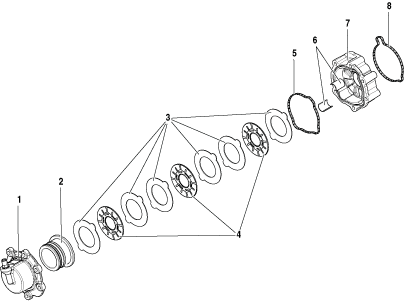 |
1. Inertia Brake Cover 2. Inertia Brake Piston 3. Steel Discs (x6) 4. Friction Discs (x3) 5. Seal - Front 6. Wear Guides (x2) 7. Inertia Brake Housing 8. Seal - Rear |
Disassemble the Inertia Brake
Remove the clutch pack from the Inertia Brake Housing.
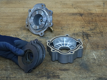
Remove the 2 wear guides from the Inertia Brake Housing.
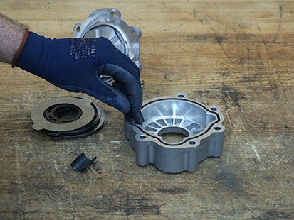
Remove Seal from the front of the Inertia Brake Housing.
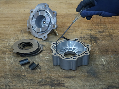
Remove Seal from the rear of the Inertia Brake Housing.
Assemble the Inertia Brake
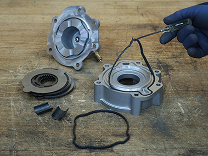
Insert the Seal into the groove on the rear of the Inertia Brake Housing until fully seated.
Note: Reference RRMT0027 - Clutch Housing Front Cover Kit for new Inertia Brake Housing part number, additional O-ring part number, and installation instructions.
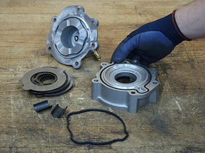
Insert the Seal into the groove on the front of the Inertia Brake Housing until fully seated.
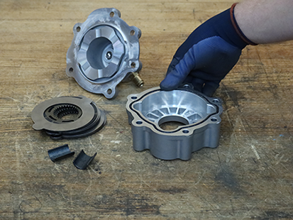
Install the 2 Wear Guides in the Inertia Brake Housing.
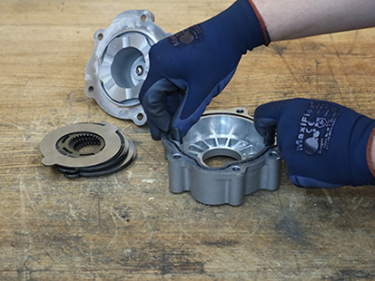
Install the inertia brake clutch pack in the order shown below:
- 1 Steel Disc,
- 1 Friction Disc,
- 2 Steel Discs,
- 1 Friction Disc,
- 2 Steel Discs,
- 1 Friction Disc, and
- 1 Steel Disc.
Note: Steel Discs align with Wear Guides. Friction Discs spline to the lower countershaft.
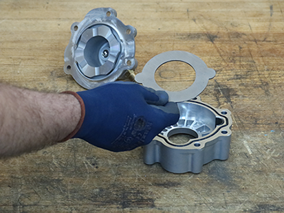
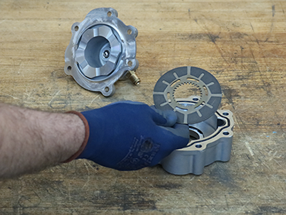
Place Inertia Brake Cover and Piston on the Housing. Align the bolt holes.