New Replacement Transmission Control Module (TCM) Service Procedure
Special Instructions
- This procedure is only performed when installing a new replacement TCM.
- Connect ServiceRanger and create a Service Activity Report prior to performing service procedure.
- Complete this entire procedure to ensure proper transmission operation after TCM installation.
Note: If reinstalling original equipment TCM, go to Transmission Control Module (TCM).
Special Tools
- ServiceRanger
Component Identification
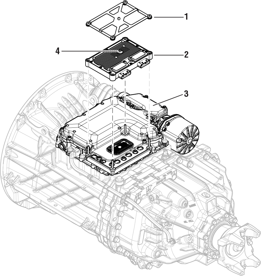 |
1. Transmission Control Module (TCM) Cover - 10 or 13 mm Nuts 2. Transmission Control Module (TCM) 3. Mechatronic Transmission Module (MTM) 4. Transmission Control Module (TCM) Jackscrew - 7 mm |
Vehicle Setup
Park vehicle on level ground.
Apply vehicle parking brake and chock wheels.
Warning
Create a Service Activity Report
Key on with engine off.
Connect ServiceRanger and create a Service Activity Report.
Select “Send to Eaton” (internet connection required)
Disconnect ServiceRanger.
Key off.
Note: If a Service Activity Report or TCM configuration template could not be created on the original equipment TCM, continue with TCM removal and installation.
Create Configuration Template
Key on with engine off.
Connect ServiceRanger.
Go To Configuration.
Select “Save a new configuration template” icon.
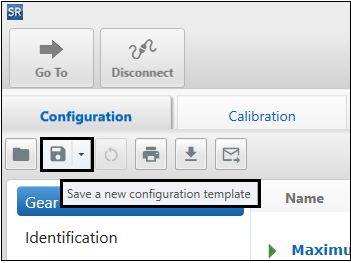
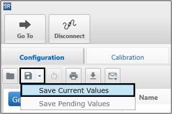
Select “Save Current Values”.
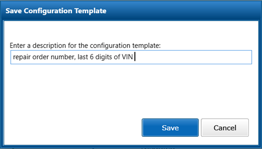
Enter repair order number, last 6 digits of VIN and select “Save”.
Disconnect ServiceRanger.
Key off.
Disconnect the Transmission Control Module (TCM)
Disconnect the negative battery cable.
NoticeDisconnect both 20-Way TCM Vehicle and Body Harness Connectors from the TCM by depressing the lock tab and lifting up on the lever.
Notice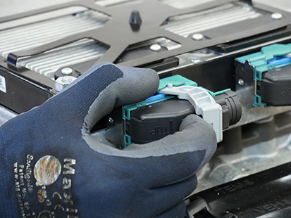
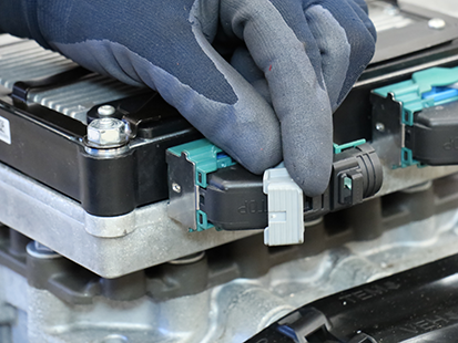
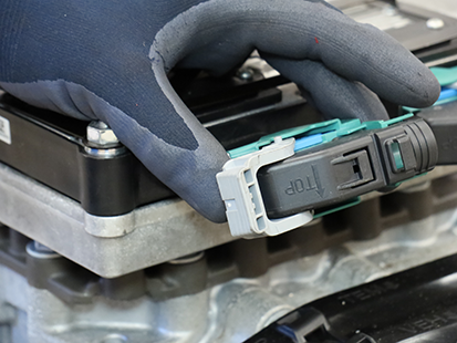
Remove the Transmission Control Module (TCM)
Unscrew the 4 TCM Cover nuts and remove TCM Cover.
Note: TCM Cover nuts are 10 or 13 mm.
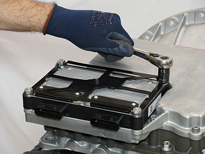
Unscrew the TCM 7 mm Jackscrew. Lift and remove the TCM from the MTM.
Notice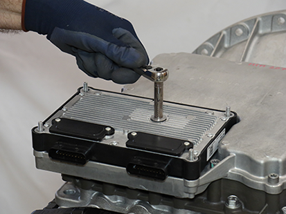
Inspect the TCM Seal for damage.
NoticeNote: If replacing the TCM, the REMAN TCM includes a new seal.
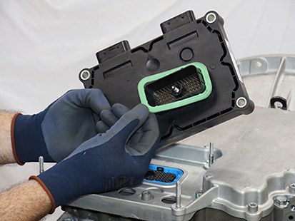
Install the Transmission Control Module (TCM)
Note: TCM can be installed with transmission in-vehicle.
Install the TCM Seal on the 74-Way Harness Connector.

Align the TCM to the 74-Way Harness Connector and TCM studs, then install the TCM.
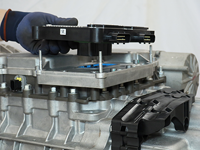
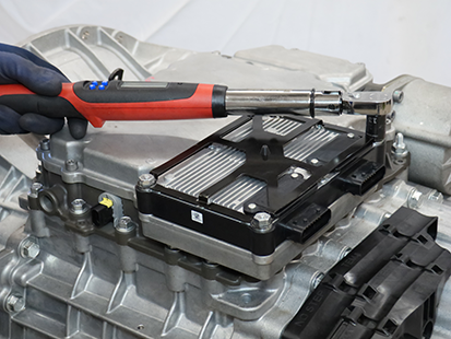
Torque the TCM 7 mm Jackscrew to 3.0-4.0 Nm (26.6-35.4 lb-in).
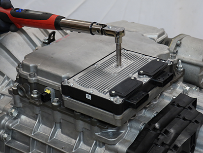
Install the TCM Cover over the 4 TCM studs and torque the 4 TCM Cover Nuts to 8.8-10.4 Nm (78-92 lb-in) in a criss-cross pattern.
Note: TCM Cover nuts are 10 or 13 mm.
Connect the Transmission Control Module (TCM).
Connect both 20-Way TCM Vehicle and Body Harness Connectors to the TCM by pressing the lever into the locked position.


Connect the negative battery cable.
Configure Transmission Control Module (TCM)
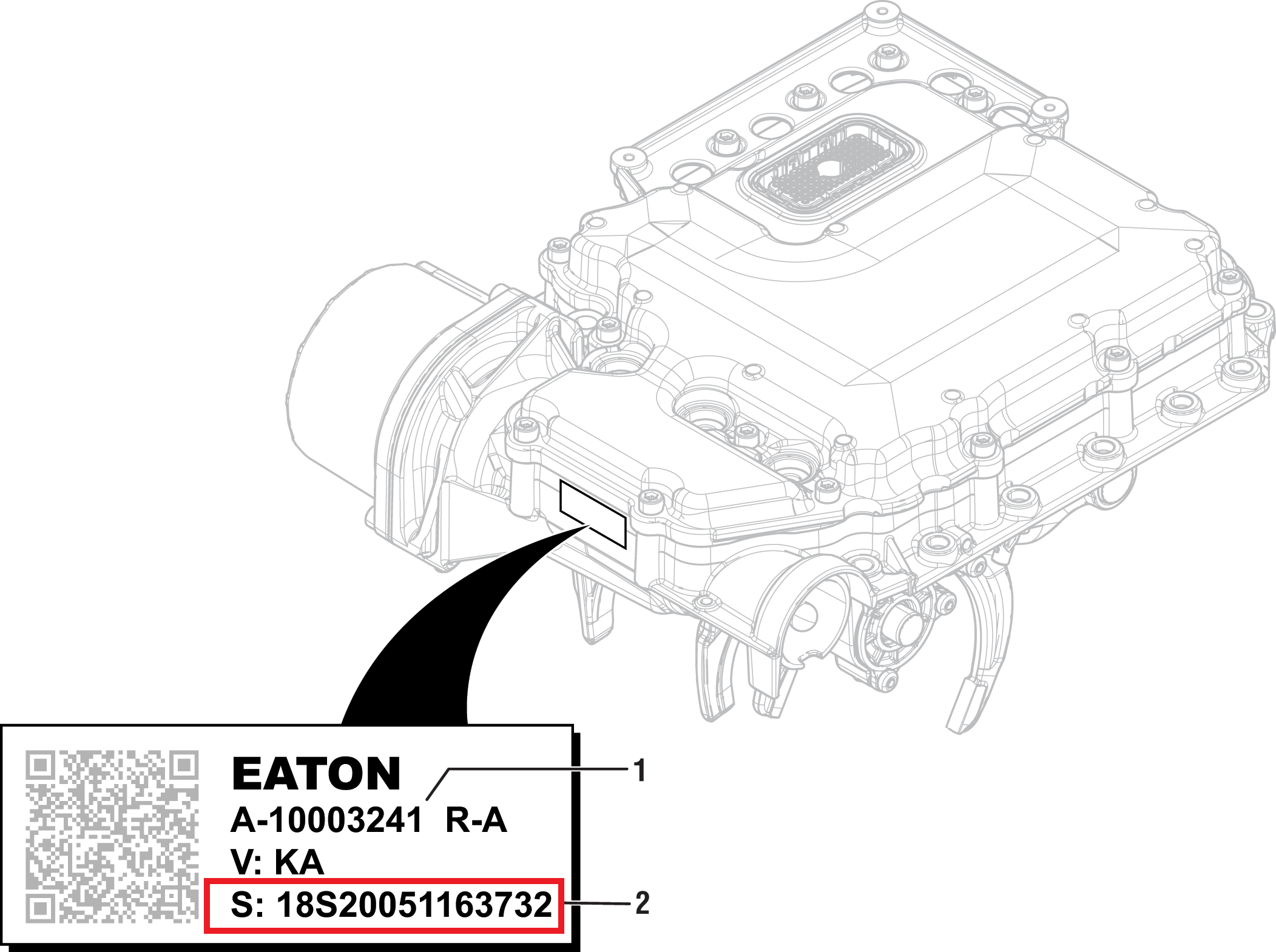
Enter current transmission serial number and MTM serial number into new replacement TCM.
Record transmission serial number.

Record MTM serial number.
Key on with engine off.
Note: Vehicle display may indicate a flashing “F”, “CC”, or service transmission.
Connect ServiceRanger.
Go To “Configuration”.
Select “Identification”.
In the “Serial Number” parameter “New Value” field enter transmission serial number.
In the “Current MTM Serial Number” parameter “New Value” field enter MTM serial number.
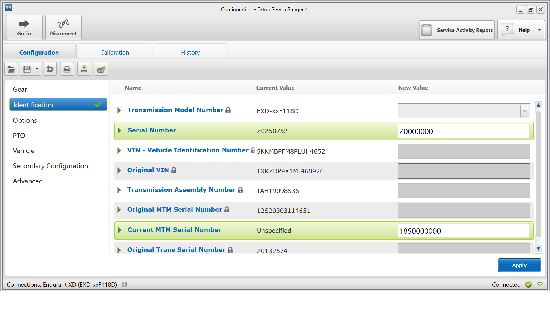
Select “Apply” and follow on-screen prompts.
Install Configuration Template into New Replacement TCM
Note: If a Service Activity Report or TCM configuration template could not be created on the original equipment TCM, contact Eaton Cummins Automated Transmission Technologies for further diagnostic instructions:
- U.S. and Canada Help Line: +1-800-826-4357
- Mexico Help Line: +52-800-800-6801
Key on with engine off.
Connect ServiceRanger.
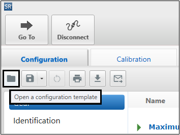
Go To Configuration.
Select “Open a configuration template” icon:
Select “Saved” tab.
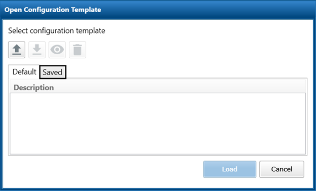
Select configuration template created at the beginning of this procedure (repair order number, last 6 digits of VIN).
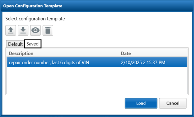
Select “Load”.
Select “Apply” (lower right corner) and follow on-screen prompts.
Configure Engine Calibration
Engine may not crank due to engine calibration not configured in TCM. Engine calibration is specific to vehicle make, engine model, and engine EPA model year(s).
Key on with engine off.
Connect ServiceRanger.
Go To “Configuration”.
Select “Calibration” tab.
Record status of Base Calibration.
- If “Your calibration is up-to-date”, go to Perform Grade Sensor Calibration.
- If “Your calibration is out-of-date”, contact Eaton Cummins Automated Transmission Technologies for further diagnostic instructions:
- U.S. and Canada Help Line: +1-800-826-4357
- Mexico Help Line: +52-800-800-6801
Perform Grade Sensor Calibration
Key on with engine off.
Connect ServiceRanger.
Go To “Service Routines”.
Select “Start” Grade Sensor Calibration and follow on-screen prompts.
Clutch and Rail Calibrations - Automatically Initiated
To ensure proper transmission operation after TCM installation, TCM, MTM, and clutch transmission need to be calibrated. Calibrations automatically initiate after vehicle air system pressure reaches operating range (approximately 100 psi).
Key on with engine running.
Allow vehicle air pressure to build to governor cut-off.
Note: Clutch and Rail Calibrations automatically initiate when vehicle air pressure reaches approximately 100 psi.
Ensure “N” (Neutral) is selected and engine is running. Wait approximately 2 minutes for calibrations to complete.
Notice- If vehicle display indicates a solid “N” (Neutral) in gear display, calibrations are complete. Key off, go to Step 5.
- If vehicle display continues to indicate a flashing “CC” and/or “F” in gear display or service transmission message, go to Step 4.
Key off and wait 1 minute.
Key on with engine off.
Connect ServiceRanger.
Go to “Fault Codes”.
- If an Active fault code is set, go to Endurant XD Troubleshooting Guide TRTS0960.
- If NO Active fault codes set, select “Clear Eaton Faults” and follow on-screen prompts.
Disconnect ServiceRanger.
Key off.
Process complete.