Fault Code 17: Start Enable Relay
J1587: MID 130 SID 237 FMI 3, 4, 14
J1939: SA 3 SPN 1321 FMI 3, 4, 14
Overview
Vehicles with an UltraShift PLUS transmission are required to disable engine cranking when the transmission is in a non-neutral gear position. Some vehicles prevent non-neu-tral engine cranking through the use of a normally open Start Enable Relay actuated by the Transmission Electronic Control Unit (TECU) to interrupt power to the Starter. Other vehicles require the TECU to send a transmission engine crank enable message over the J1939 Data Link before the engine ECU will allow cranking. The Start Enable Relay cir-cuit is supplied and wired by the OEM.
For vehicles equipped with a physical Start Enable Relay cir-cuit, the relay will only latch when the following three condi-tions exist:
- Driver Interface Device is in the neutral position.
- Transmission has confirmed that it is physically in neutral.
- Engine is not running.
Under these conditions the TECU supplies a voltage source and a ground path to the Start Enable Relay coil, latching the relay. The latched relay allows Engine-Starter engage-ment when the ignition key is turned to the crank position. If these conditions are not met, the TECU removes the volt-age source and ground path to the Start Enable Relay, opening the relay and preventing engagement of the Starter.
Fault Code 17 indicates that an electrical failure in the Start-Enable Relay circuit was detected. The fault will not set on vehicles that use J1939 messaging to enable engine cranking.
Detection
This fault can only be detected on transmission systems that are configured for Start Enable Relay. When the ignition key is on, the engine is not running, and the Start Enable Relay coil is not latched, this fault can be detected.
Conditions to Set Fault Code Active
FMI 3 – Voltage Above Normal or Shorted High: TECU detects a short to voltage or an open circuit for at least 1 second.
FMI 4 – Voltage Below Normal or Shorted Low: TECU detects a short to ground for at least 1 second.
FMI 14 – Special Instructions: TECU detects an engine start when the Start Enable Relay was not intentionally latched. This is typically an indication that the Start Enable Relay circuit is incorrectly wired or bypassed (jumped).
Fallback
FMI 3, 4:
- “F” flashes in gear display.
- Service light flashes (if equipped).
- Engine will not crank.
FMI 14:
- “F” flashes in gear display.
- Service light flashes (if equipped).
- If the Start Enable Relay circuit is incorrectly wired or bypassed (jumped), the TECU may not be able to prevent the engine from cranking when the transmission is in a non-neutral position.
Conditions to Set Fault Code Inactive
FMI 3, 4: An electrical short or open circuit is not detected for 2 seconds.
FMI 14: Start Enable Relay wiring issue is corrected and Start Enable Relay fault code is unlatched.
Possible Causes
FMI 3, 4:
- Start Enable Relay
- Internal Failure
- Start Enable Relay Wiring
- Bent, spread, corroded or loose terminals
- Wiring shorted to ground, shorted to power or open
- TECU
- Internal Failure
FMI 14:
- Start Enable Relay
- Internal Failure
- Start Enable Relay Wiring
- Incorrectly wired
- Bypassed (jumped) Start Enable Relay circuit
Component Identification
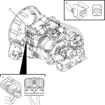 |
1. 38-Way Vehicle Harness Connector 2. Transmission Electronic Control Unit (TECU) 3. 5-Way Start Enable Relay Socket |
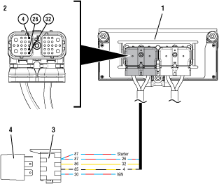 |
1. Transmission Electronic Control Unit (TECU) 2. 38-Way Vehicle Harness Connector 3. 5-Way Start Enable Relay Socket 4. 5-Way Start Enable Relay |
 |
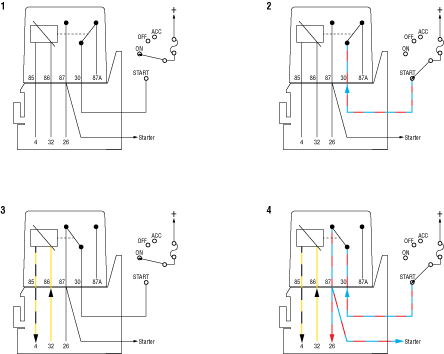 |
Start Enable Relay Circuit States (Normally Open) 1. Open Relay - Key On and Transmission is Unable to Confirm Neutral 2. Open Relay - Key Start and Transmission is Unable to Confirm Neutral 3. Closed Relay - Key On and Transmission Confirmed in Neutral 4. Closed Relay - Key Start and Transmission Confirmed in Neutral |
 |
Fault Code 17 Troubleshooting
Record the transmission fault codes, FMIs, occur-rences, and timestamps from the Service Activity Report created during the Diagnostic Procedure.
Note: If Fault Code 17 is Inactive and engine cranks, but does not run, troubleshoot vehicle engine system per OEM recommendations.
Note: Some OEMs and chassis may use an alter-nate wiring pattern, which may include the use of a second relay for other vehicle systems. Please con-sult chassis specific OEM wiring schematics and verify which relay is in place for the Eaton automated transmission.
If Fault Code 17 FMI 14 is Active, Go to Step B
If Fault Code 17 FMI 14 is Inactive, Start Enable Relay may have been incorrectly wired and repaired or bypassed (jumped). Test complete, Go to Step V
If Fault Code 17 FMI 3 or 4 is Active, Go to Step D
If Fault Code 17 FMI 3 or 4 is Inactive, Go to Step C
Set parking brake and chock wheels.
Key off.
Verify the Start Enable Relay circuit is correctly connected and wired per the wiring diagram. Con-sult OEM for specific wire routing locations. Cor-rect wire routing if necessary.
Key on with engine off.
Wait for Neutral (N) to appear in the gear display

Turn and hold the key in the crank position for 5 seconds. A momentary crank should occur, but will be interrupted after 0.5 second. This test verifies the transmission can interrupt the Start Enable Relay circuit. The system does not allow engine cranking until the next power-up cycle.
Key off.
NoticeKey on with engine off.
Connect ServiceRanger.
Retrieve and record the transmission fault codes and FMIs, and their occurrences and timestamps.
If Fault Code 17 FMI 14 is now Inactive and the engine will now crank, Start Enable Relay may have been incorrectly wired and repaired or bypassed (jumped). Test complete, Go to Step V
If Fault Code 17 FMI 14 is Active or engine will not crank, Go to Step F
Set parking brake and chock wheels.
Place transmission in PD Mode. See more about Product Diagnostic (PD) Mode

Wiggle Start Enable Relay wiring from the 38-Way Vehicle Harness Connector to the Start Enable Relay. Look for signs of rubbing or chafing. Consult OEM for specific wire routing locations.
Exit PD Mode by powering down.
Notice
If Fault Code 17 became Active during wiggle wire test, repair or replace the Start Enable Relay wiring per OEM requirements. Go to Step V
If Fault Code 17 remains Inactive, Go to Step E
Key off.
NoticeKey on with engine off.
Connect ServiceRanger.
Select “Configuration”.
Select “Vehicle”.
Record the “Current Value” for the “Start Enable Type”.
Record the “Start Enable Type” installed on the vehicle.
Note: The vehicle's “Start Enable Type” (hardwired relay or J1939 controlled), is determined by the OEM. Refer to the OEM regarding “Start Enable Type” installed on the vehicle.
Compare reading(s) in table.
If “Start Enable Type” is configured correctly, Go to Step E
If “Start Enable Type” is not configured cor-rectly, select the correct configuration from the “New Value” drop down, select “Apply” and follow on screen prompt. Go to Step V
| Location | Start Enable Type |
|---|---|
| TECU (ServiceRanger) | |
| Vehicle |
Key off.
Remove Start Enable Relay
Inspect Relay Connector body for damage and bent, spread, corroded or loose terminals.
Key on with engine off.
Wait for Neutral (N) to appear in the gear display.
Note: Flashing “F” may appear in the gear display.
Measure voltage between Start Enable Relay socket Pin 86 (power) and Pin 85 (ground). Record read-ing(s) in table.
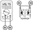
Compare reading(s) in table.
If all readings are in range, Go to Step F
If any readings are out of range, Go to Step G
| Pins | Range | Reading(s) |
|---|---|---|
| 85 to 86 | Within 1.5 V of Battery Voltage |
Key off.
Determine if vehicle uses a 12-volt or a 24-volt electrical system.
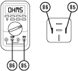
Measure the resistance across relay Pin 85 and Pin 86. Record reading(s) in table.
Note: The allowable relay resistance range is differ-ent for 12-volt and 24-volt systems.
Measure the resistance across relay Pin 30 and Pin 87. Record reading(s) in table.
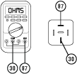
Compare reading(s) in table.
If readings are in range, Go to Step G
If readings are out of range, replace Start Enable Relay. Go to Step V
| Pins | Range | Reading(s) |
|---|---|---|
| 85 to 86 | 12 V System 40–200 Ohms | |
| 24 V System 40–500 Ohms | ||
| 30 to 87 | Open Circuit (OL) |
Key off.
Disconnect the 38-Way Vehicle Harness Connector at the TECU.
Inspect 38-Way Connector body for damage and bent, spread, corroded or loose terminals.
Remove the Start Enable Relay.
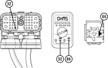
Measure resistance between 38-Way Vehicle Har-ness Connector Pin 32 and Start Enable Relay socket Pin 86. Record reading(s) in table.
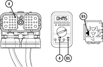
Measure resistance between 38-Way Vehicle Har-ness Connector Pin 4 and Start Enable Relay socket Pin 85. Record reading(s) in table.
Measure resistance between 38-Way Vehicle Har-ness Connector Pin 26 and Start Enable Relay Socket Pin 87. Record reading(s) in table.
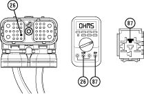
Compare reading(s) in table.
If all readings are in range, Go to Step H
If readings are out of range, repair or replace the Start Enable Relay wiring per OEM guide-lines. Go to Step V
| Pins | Range | Reading(s) |
|---|---|---|
| VH 32 to SER 86 | 0.0–0.3 Ohms | |
| VH 4 to SER 85 | 0.0–0.3 Ohms | |
| VH 26 to SER 87 | 0.0–0.3 Ohms |
Key off.
Measure resistance between 38-Way Vehicle Har-ness Connector Pin 4 and ground. Record read-ing(s) in table.
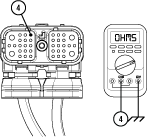
Measure resistance between 38-Way Connector Pin 4 and Battery Positive (+). Record reading(s) in table.
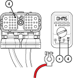
Compare reading(s) in table.
If all readings are in range, Go to Step I
If readings are out of range, repair or replace the Vehicle Harness per OEM guide-lines. Go to Step V
| Pins | Range | Reading(s) |
|---|---|---|
| 4 to Ground | Open Circuit (OL) | |
| 4 to Battery Positive (+) | Open Circuit (OL) |
Key off.
Measure resistance between 38-Way Vehicle Har-ness Connector Pin 32 and ground. Record read-ing(s) in table.
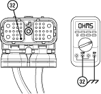
Measure resistance between 38-Way Vehicle Har-ness Connector Pin 32 and Battery Positive (+). Record reading(s) in table.
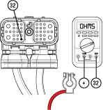
Compare reading(s) in table.
If all readings are in range, Go to Step J
If readings are out of range, repair or replace the Vehicle Harness per OEM guide-lines. Go to Step V
| Pins | Range | Reading(s) |
|---|---|---|
| 32 to Ground | Open Circuit (OL) | |
| 32 to Battery Positive (+) | Open Circuit (OL) |
Key off.
Measure voltage between Start Enable Relay socket Pin 87 and ground. Record reading(s) in table.
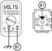
Compare reading(s) in table.
If all readings are in range, Go to Step K
If readings are out of range, repair or replace the Start Enable Relay Latch wire per OEM guide-lines. Go to Step V
| Pins | Range | Reading(s) |
|---|---|---|
| 87 to Ground | Less than 0.5 volt |
Verify which FMI was set for Fault Code 17 in Step A.
If Fault Code 17 FMI 3 or 4 was set, Go to Step L
If Fault Code 17 FMI 14 was set, Go to Step M
Set parking brake and chock wheels.
Key off.
Verify the Start Enable Relay circuit is correctly connected and wired per the wiring diagram. Con-sult OEM for specific wire routing locations. Cor-rect wire routing if necessary.
Key on with engine off.
Wait for Neutral (N) to appear in the gear display.

Attempt to crank the engine.
If Fault Code 17 FMI 3 or 4 is now Inactive and the engine will now crank, no problem was found. The intermittent nature of the fault makes it likely that the problem is in the Start Enable Relay wiring. Contact OEM for further help troubleshooting the wiring. Go to Step V
If Fault Code 17 FMI 3 or 4 is Active, replace Transmission Electronic Control Unit (TECU). Go to Step V
Set parking brake and chock wheels.
Key off.
Verify the Start Enable Relay circuit is correctly connected and wired per the wiring diagram. Con-sult OEM for specific wire routing locations. Cor-rect wire routing if necessary.
Key on with engine off.
Wait for Neutral (N) to appear in the gear display.

Turn and hold the key in the crank position for 5 seconds. A momentary crank should occur, but will be interrupted after 0.5 second. This test verifies the transmission can interrupt the Start Enable Relay circuit. The system does not allow engine cranking until the next power-up cycle.
Key off.
NoticeKey on with engine off.
Connect ServiceRanger.
Retrieve and record the transmission fault codes and FMIs, and their occurrences and timestamps.
If Fault Code 17 FMI 14 is now Inactive and the engine will now crank, no problem was found. Test complete, Go to Step V
If Fault Code 17 FMI 14 is Active, replace Transmission Electronic Control Unit (TECU). Go to Step V
Key off.
Reconnect all connectors and verify that all components are properly installed.
Key on.
Clear fault codes using ServiceRanger.
Test the Start Enable Relay system by attempting to crank the Starter multiple times. Verify that the starting system operates properly.
Check for fault codes using ServiceRanger:
If no fault codes set Active and vehicle oper-ates properly, test complete.
If Fault Code 17 sets Active during the test drive, Go to Step A
If a fault code other than 17 sets Active, trou-bleshoot per Fault Code Isolation Procedure Index.