Fault Code 19: CAN Gen1 ECA Message
J1587: MID 130 SID 248 FMI 9
J1939: SA 3 SPN 520273 FMI 9
Overview
The High Integrity Link (HIL) is a Controller Area Network (CAN) high-speed proprietary data link that communicates data between the Transmission Electronic Control Unit (TECU), Electronic Clutch Actuator (ECA), and if equipped, Eaton Push Button Shift Control (PBSC). The portion of the HIL that connects the TECU to the ECA is contained within the Transmission Harness. The portion of the HIL that connects the TECU to the PBSC is contained within the Vehicle Harness. Fault Code 19 indicates a loss of communication between the TECU and ECA.
Detection
The TECU monitors communication with the ECA over the HIL. If the TECU loses communication with the ECA, Fault Code 19 sets Active.
Conditions to Set Fault Code Active
FMI 9 – Abnormal Update Rate: TECU loses communication with the ECA for 2 seconds or longer.
Fallback
FMI 9
- “F” flashes in gear display.
- Service light flashes (if equipped).
- Engine cranks and starts.
- Transmission may not engage a gear from neutral.
- ECA may maintain the current clutch position using the clutch holding device.
- ECA may move the clutch to the last position commanded by the TECU.
Conditions to Set Fault Code Inactive
FMI 9: TECU establishes communication with the ECA for 4 seconds.
Possible Causes
FMI 9
- Vehicle Power and Ground Supply to ECA
- Poor power or ground supply
- Bent, spread, corroded or loose terminals
- Wiring shorted to ground, shorted to power or open
- Seal failure on 3-Way Gen1 ECA Connector
- Disconnected 3-Way Gen1 ECA Connector
- Vehicle Batteries
- Internal failure
- Transmission Harness
- Wiring shorted to ground, shorted to power or open
- Bent, spread, corroded or loose terminals
- Seal failure in 8-Way Gen1 ECA Connector
- Loss of ignition voltage to ECA before power up
- ECA
- Failed ECA software download
- Bent, spread, corroded or loose terminals
- Contamination in 3-Way Gen1 ECA Connector
- Contamination in 8-Way Gen1 ECA Connector
- Internal failure
Component Identification
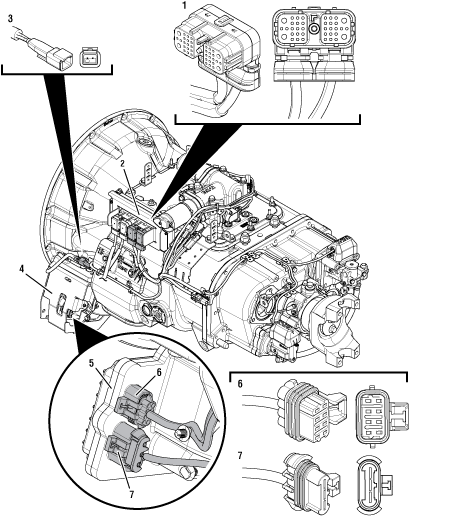 |
1. 38-Way Transmission Harness Connector 2. Transmission Electronic Control Unit (TECU) 3. 2-Way Terminating Resistor Connector Body 4. Gen1 ECA Shield 5. Gen1 Electronic Clutch Actuator (ECA) 6. 8-Way Gen1 ECA Connector 7. 3-Way Gen1 ECA Connector |
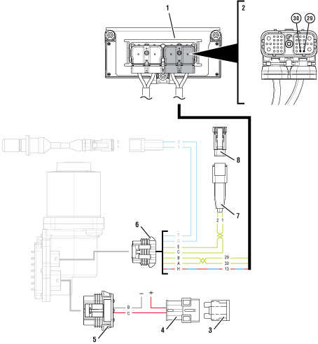 | |
1. Transmission Electronic Control Unit (TECU) 2. 38-Way Transmission Harness Connector 3. 40-amp Fuse 4. In-line Fuse Holder 5. 3-Way Gen1 ECA Connector | 6. 8-Way Gen1 ECA Connector 7. 2-Way Terminating Resistor Connector Body 8. 2-Way High Integrity Link (HIL) Terminating Resistor |
 |
Fault Code 19 Troubleshooting Gen1 ECA
Set parking brake and chock wheels.
Inspect ECA OEM Power Supply Connector, reference image below.
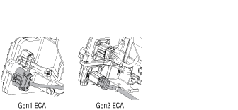
If equipped with a Gen1 ECA, Go to Step B
If equipped with a Gen2 ECA, go to Fault Code 19: CAN Gen2 ECA Message.
Determine if vehicle manufacturer isPACCAR.
If vehicle is not manufactured by PACCAR, Go to Step C
If vehicle is manufactured by PACCAR, Go to Step S
Determine if an ECA software download was performed immediately before Fault Code 19 set Active.
Note: If an ECA software download fails to complete, the transmission will set Fault Code 19 and may also set Fault Code 16.
If an ECA software download was not recently performed, Go to Step E
If Fault Code 19 became Active immediately following an ECA software download, download may have failed. Go to Step D
Key off.
Note: Allow 2–3 minutes for the TECU to perform a complete power-down sequence before proceeding.
Key on with engine off.
Connect ServiceRanger.
Use ServiceRanger to program or recover the TECU and ECA software to latest available levels.
If software does not download correctly, contact Eaton at (800) 826-4357.
If software downloads correctly and Fault Code 19 becomes Inactive, test complete. Go to Step V
If software downloads correctly, but Fault Code 19 remains Active, Go to Step E
Record the transmission fault codes, FMIs, occurrences, and timestamps from the Service Activity Report created during the Diagnostic Procedure.
Check vehicle cab to determine the type of Shift Control Device installed on the vehicle.

If equipped with an Eaton PBSC, Go to Step F
If equipped with any other shift device, including an Eaton Cobra Lever or an OEM Shift Device, Go to Step G
Retrieve fault code information from the Service Activity Report.
If Fault Code 16 is Active, troubleshoot per Fault Code Isolation Procedure.
If Fault Code 19 is Active and Fault Code 16 is Inactive or not set, Go to Step I
If Fault Code 19 is Inactive, Go to Step H
Retrieve fault code information from the Service Activity Report.
If Fault Code 19 is Active, Go to Step I
If Fault Code 19 is Inactive, Go to Step H
Set parking brake and chock wheels.
Place transmission in PD Mode. See more about Product Diagnostic (PD) Mode.
Note: Transmission does not enter PD Mode when Active fault codes exist.

Wiggle wiring and connections from the batteries to the 3-Way Connector at the ECA. Look for signs of pinched or chafed wiring. Verify all connections are clean and tight.
Wiggle wiring and connections of the Transmission Harness from the 8-Way Gen1 ECA Connector to the 38-Way Vehicle Harness Connector at the TECU.
Exit PD Mode by powering down.
Note: Allow 2–3 minutes for the TECU to perform a complete power-down sequence before proceeding.
If any fault became Active while wiggling the 3-Way Connector to the ECA, refer to OEM guidelines for repair or replacement of the ECA Power Harness. Go to Step V
If any fault became Active while wiggling the Transmission Harness, replace Transmission Harness. Go to Step V
If no fault codes set Active, Go to Step I
Key off.
Inspect the ECA Power Supply Harness between the batteries and the ECA for signs of rubbing or chafing to the wiring.
Inspect the ECA 40-amp In-line Fusible Link or Fuse Holder Con-nections for damage and bent, spread, corroded or loose terminals.
Note: Some chassis use a power and ground distri-bution block separate from the battery or may route power and ground to the starter. Be sure to clean and inspect connections at this location and at the battery.
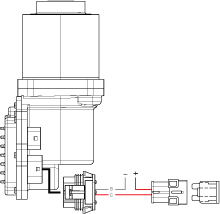
If damage to the ECA Power Supply Harness is found, refer to OEM guidelines for repair or replacement. Go to Step V
If no damage is found, Go to Step J
Key off.
Disconnect 3-Way Gen1 ECA Connector.
Verify connector is free from any corrosion; the ter-minals are not bent, spread or loose; and there is no damage to the connector body.
Confirm the 3-Way Gen1 ECA Connector has a seal plug in Cavity A.
Inspect ECA side of 3-Way Gen1 ECA Connector, verify connector is free from any corrosion, the terminals are not bent, spread or loose; and there is no damage to the connector body.
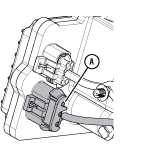
If damage to the 3-Way Gen1 ECA Connector is found and/or missing seal plug in Cavity A, refer to OEM guidelines for repair or replace-ment. Go to Step V
If damage to the ECA side of 3-Way Gen1 ECA Connector is found, replace Electronic Clutch Actuator (ECA). Go to Step V
If no damage is found, Go to Step K
Key off.
Measure voltage between 3-Way Gen1 ECA Connector Pin C (Battery positive) and Pin B (Battery nega-tive). Record reading in table.
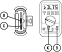
Compare reading(s) in table.
If readings are out of range, refer to OEM guidelines for repair or replacement of the ECA Power Supply Harness. Go to Step V
If readings are in range, Go to Step L
| Pins | Range | Reading(s) |
|---|---|---|
| C to B | Within 1.2 V of Battery Positive (+) |
Key off.
Measure voltage between 3-Way Gen1 ECA Connector Pin C (Battery positive) and ground. Record read-ing(s) in table.
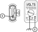
Compare reading in table.
If readings are out of range, Pin C (Battery posi-tive) and Pin B (Battery negative) wires are incorrectly pinned in the ECA 3-Way Connector. Refer to OEM requirements for repair or replacement. Go to Step V
If readings are in range, Go to Step M
| Pins | Range | Reading(s) |
|---|---|---|
| C to Ground | Within 1.2 V of Battery Positive (+) |
Key off.
Load test the 3-Way Gen1 ECA Connector and ECA Power Supply Harness with an external load source. Use a sealed beam headlamp or blower motor attached to Pin C (Battery positive) and Pin B (Battery negative). Load Test for 5 minutes to verify the harness will carry a load with the 40-amp fuse or fusible link installed.

Wiggle the ECA Power Supply Harness during the Load Test from the vehicle batteries to ECA.
If the ECA Power Supply Harness does not carry a load, refer to OEM guidelines for repair or replacement. Go to Step V
If the ECA Power Supply Harness carries a load, Go to Step N
Key off.
Disconnect 8-Way Gen1 ECA Connector.
Verify connector is free from any corrosion; the terminals are not bent, spread or loose; and there is no damage to the connector body.
Inspect the Transmission Harness from the TECU to the 8-Way Gen1 ECA Connector. Look for signs of rubbed or chafed wiring.
Inspect ECA side of 8-Way Gen1 ECA Connector, verify connector is free from any corrosion, the terminals are not bent, spread or loose; and there is no damage to the connector body.
If damage is found to the 8-Way Gen1 ECA Connector, replace Transmission Harness. Go to Step V
If damage is found to the ECA side of 8-Way Gen1 ECA Connector, replace Electronic Clutch Actuator (ECA). Go to Step V
If no damage is found, Go to Step O
Key on with engine off.
Measure voltage between 8-Way Gen1 ECA Pin H and ground. Record reading in table.
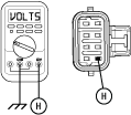
Compare reading(s) in table.
If readings are in range, Go to Step P
If readings are out of range, replace Transmission Harness. Go to Step V
| Pins | Range | Reading(s) |
|---|---|---|
| H to Ground | Within 1.2 V of Battery Voltage |
Key off.
Disconnect 38-Way Transmission Harness Connector.
Verify connector is free from any corrosion; the terminals are not bent, spread or loose; and there is no damage to the connector body.
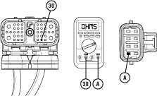
Measure resistance between 38-Way Transmission Harness Connector Pin 30 and 8-Way Gen1 ECA Connector Pin A. Record reading in table.
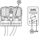
Measure resistance between 38-Way Transmission Harness Connector Pin 30 and ground. Record reading in table.
Compare reading(s) in table.
If readings are in range, Go to Step Q
If readings are out of range, replace Transmission Harness. Go to Step V
| Pins | Range | Reading(s) |
|---|---|---|
| 30 to A | 0.0–0.6 ohms | |
| 30 to Ground | Open Circuit (OL) |
Key off.
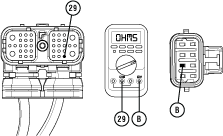
Measure resistance between 38-Way Transmission Harness Connector Pin 29 and 8-Way Gen1 ECA Connector Pin B. Record reading in table.
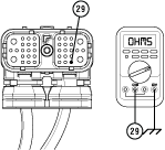
Measure resistance between 38-Way Transmission Harness Connector Pin 29 and ground. Record reading in table.
Compare reading(s) in table.
If readings are in range, Go to Step R
If readings are out of range, replace Transmission Harness. Go to Step V
| Pins | Range | Reading(s) |
|---|---|---|
| 29 to B | 0.0–0.6 ohms | |
| 29 to Ground | Open Circuit (OL) |
Key off.
Reconnect 3-Way Gen1 ECA Connector.
Reconnect 8-Way Gen1 ECA Connector.
Reconnect 38-Way Transmission Harness Connector.
Locate and remove the 2-Way HIL Terminating Resistor from the 2-Way Terminating Resistor Connector Body wired into the 8-Way Gen1 ECA Connector (Transmission Harness).
Note: Reference the Component Identification section.
Inspect the 2-Way Terminating Resistor Connector Body for damage and bent, spread, corroded or loose terminals.
Measure resistance at the 2-Way Terminating Resistor Connector Body wired into the 8-Way Gen1 ECA Connector (Transmission Harness) between Pin 1 and Pin 2. Record reading in table.

Note: The resistance of the HIL varies based on the transmission shift device equipped in the vehicle.
Reinstall the 2-Way HIL Terminating Resistor into the 2-Way Terminating Resistor Connector Body.
Compare reading(s) in table.
If readings are out of range, replace Transmission Harness. Go to Step V
If readings are in range, replace Electronic Clutch Actuator (ECA).Go to Step V
| Pins | Range | Reading(s) |
|---|---|---|
| 1 to 2 (with Eaton PBSC) | 50–70 ohms | |
| 1 to 2 (without Eaton PBSC) | 110–130 ohms |
Refer to TAIB-0883.
If TAIB-0883 has not been completed, perform TAIB-0883.
f vehicle does not meet criteria of TAIB-0883 or if TAIB-0883 was already completed, Go to Step C
Key off.
Reconnect all connectors and verify that all components are properly installed.
Key on with engine off.
Clear fault codes using ServiceRanger.
Drive vehicle and attempt to reset the code or duplicate the previous complaint.
Check for fault codes using ServiceRanger.
If no codes set Active and vehicle operates properly, test complete.
If Fault Code 19 sets Active contact Eaton at 1-800-826-4357 for further diagnostics.
If a fault code other than 19 sets Active, troubleshoot per Fault Code Isolation Procedure Index.