Fault Code 43: Range Solenoid Valve
J1587: MID 130 SID 35 FMI 3, 4, 5, 6, 8, 12, 18
MID 130 SID 36 FMI 3, 4, 5, 6, 8, 12, 18
J1939: SA 3 SPN 768 FMI 3, 4, 5, 6, 8, 12, 18
SA 3 SPN 769 FMI 3, 4, 5, 6, 8, 12, 18
Overview
Most UltraShift PLUS Transmission models are equipped with a 2-speed range system in the auxiliary case. The ability to select an auxiliary range gear independently from a main case gear allows the transmission twice the number of overall gear ratios by using the main case gearing once in auxiliary low range and again in auxiliary high range.
The range system is equipped with a Range Solenoid Valve. The Range Solenoid Valve is an electric-over-air solenoid that is controlled by the Transmission Electronic Control Unit (TECU), replacing the Shift Knob-Slave Valve system found on Eaton Cummins Automated Transmissions.
During operation, the solenoid directs air pressure to either port in the Range Cylinder based on the need to activate the auxiliary low range or high range gearing. The applied air pressure directs the fore-and-aft movement of the Range Piston within the Range Cylinder, facilitating the mechanical engagement of the Range Synchronizer into either low or high range. Auxiliary case gear changes are physically engaged and disengaged to the transmission main case through the Range Synchronizer.
Fault Code 43 indicates an electrical fault within the Range Solenoid Valve circuit.
Detection
The TECU can detect an open circuit or a short to ground when the Range Solenoid Valve is on. The TECU can detect a short to power when the Range Solenoid Valve is off.
Conditions to Set Fault Code Active
FMI 3 – Voltage Above Normal or Shorted High: With the solenoid off, the TECU detects high voltage in the Range Solenoid Valve high side driver circuit for 1 second.
FMI 4 – Voltage Below Normal or Shorted Low: With the solenoid on, the TECU detects low voltage in the Range Solenoid Valve low side driver circuit for 1 second.
FMI 5 – Current Below Normal or Open Circuit: With the solenoid on, the TECU detects an open in the Range Solenoid Valve circuit for 1 second.
FMI 6 – Current Above Normal or Shorted Circuit: TECU detects a short to power on the Range Solenoid Valve circuit.
FMI 8 – Abnormal Frequency: Range Solenoid Valve out of normal operating frequency.
FMI 12 – Bad Intelligent Device: Range Solenoid Valve driver internal failure.
FMI 18 – Data Valid But Below Normal (Moderately Severe): Range Solenoid Valve circuit current low and battery voltage below 9.2V when the solenoid is on.
Fallback
All FMIs
- “F” flashes in gear display.
- Service light flashes (if equipped).
- Engine cranks and starts.
- High side coil failure (SID 35/SPN 768).
- If the failure occurs in high range, the transmission shifts through all high range gears and shifts to low range when vehicle speed is appropriate; however, the transmission is then restricted to shifting in all low range gears only.
- If the failure occurs in low range, the transmission shifts through all low range gears but will not shift to high range.
- Low side coil failure (SID 36/SPN 769).
- If the failure occurs in high range, the transmission shifts through all high range gears but will not shift into low range.
- If the failure occurs in low range, the transmission shifts through all low range gears but will not shift to high range.
Conditions to Set Fault Code Inactive
FMI 3, 4, 5, 6: Splitter Solenoid Valve circuit in range for 2 seconds.
FMI 8, 12, 18: Condition no longer exists.
Possible Causes
FMI 3
- Transmission Harness
- Wiring shorted to power
- TECU
- Internal short to power
FMI 4
- Transmission Harness
- Wiring shorted to ground
- Range Solenoid Valve
- Internal short to ground
- TECU
- Internal short to ground
FMI 5
- Transmission Harness
- Open circuit
- Bent, spread, corroded or loose terminals
- Range Solenoid Valve
- Internal solenoid coil failure
- TECU
- Internal open circuit
FMI 6
- TECU
FMI 8
- Vehicle Power Supply
- Poor power or ground supply to TECU (may be in conjunction with Fault Codes 33 or 34)
- Bent, spread, corroded or loose terminals
- Wiring shorted to ground, shorted to power or open
- Vehicle Batteries
- Internal failure
- Vehicle 30-amp Battery Fuse
- Bent, spread, corroded or loose terminals
- Fuse missing or improperly seated
- TECU
- Internal failure
FMI 12
- Driver Behavior
- Driver induced ignition key cycles not allowing TECU to fully power down
- TECU
FMI 18
- Vehicle Power Supply
- Poor power or ground supply to TECU (may be in conjunction with Fault Codes 33 or 34)
- Bent, spread, corroded or loose terminals
- Wiring shorted to ground, shorted to power or open
- Vehicle Batteries
- Internal failure
- Vehicle 30-amp Battery Fuse
- Bent, spread, corroded or loose terminals
- Fuse missing or improperly seated
Component Identification
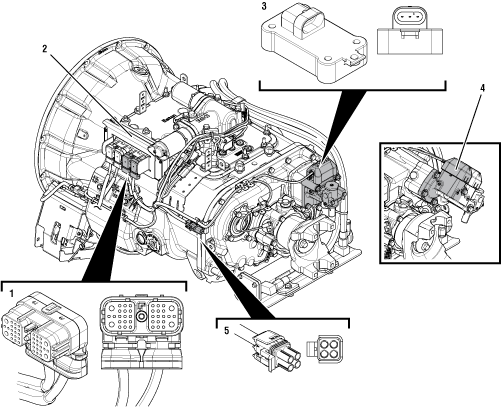 |
1. 38-Way Transmission Harness Connector- 2. Transmission Electronic Control Unit (TECU) 3. Range Solenoid Valve (LAS / VAS / MHP / VHP / MXP / LSE / VXP) 4. Range Solenoid Valve (VCS / VMS) 5. 4-Way Diagnostic Connector |
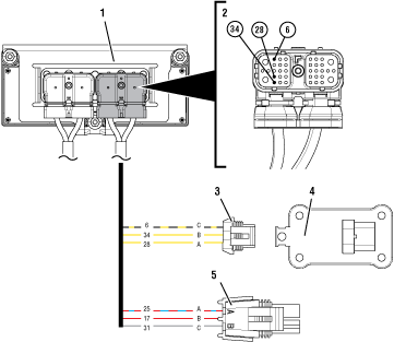 |
1. Transmission Electronic Control Unit (TECU) 2. 38-Way Transmission Harness Connector 3. 3-Way Range Solenoid Valve Connector 4. 3-Way Range Solenoid Valve 5. 4-Way Diagnostic Connector |
 |
Fault Code 43 Troubleshooting
Record the transmission fault codes, FMIs, occurrences, and timestamps from the Service Activity Report created during the Diagnostic Procedure.
Note: If Fault Code 43 is Inactive and there are other Active fault codes, troubleshoot all Active fault codes first.
If Fault Code 43 FMI 3, 4 or 5 is Active, Go to Step C
If Fault Code 43 FMI 3, 4 or 5 is Inactive, Go to Step B
If Fault Code 43 FMI 6 is Active or Inactive, replace Transmission Electronic Control Unit (TECU). Go to Step V
If Fault Code 43 FMI 12 is Active, Go to Step K
If Fault Code 43 FMI 12 is Inactive, test complete. Go to Step V
If Fault Code 43 FMI 8 or 18 is Active or Inactive, Go to Step H
Set parking brake and chock wheels.
Place transmission in PD Mode. See more about Product Diagnostic (PD) Mode.
Note: Transmission does not enter PD Mode when there are Active fault codes.

Wiggle wiring and connections. Be sure to include Transmission Harness from the Range Solenoid Valve to the TECU.
Exit PD Mode by powering down.
Notice
If Fault Code 43 or any other fault code set Active while wiggling the Transmission Harness, replace the Transmission Harness. Go to Step V
If no fault codes became Active while wiggling the Transmission Harness, Go to Step C
Key off.
NoticeDisconnect 38-Way Transmission Harness Connector from the TECU.
Inspect 38-Way Connector body for damage and bent, spread, corroded or loose terminals.
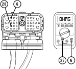
Measure resistance between 38-Way Connector Pin 28 and Pin 6. Record reading(s) in table.
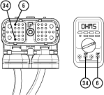
Measure resistance between 38-Way Connector Pin 34 and Pin 6. Record reading(s) in table.
Compare reading(s) in table.
If both readings are in range, Go to Step D
If either reading is out of range, Go to Step F
| Pins | Range | Reading(s) |
|---|---|---|
| 28 to 6 | 9–16 ohms | |
| 34 to 6 | 9–16 ohms |
Key off.
Measure resistance between 38-Way Transmission Harness Connector Pin 34 and ground. Record reading(s) in table.
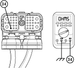
Measure resistance between 38-Way Connector Pin 28 and ground. Record reading(s) in table.
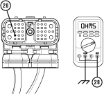
Disconnect 3-Way Range Solenoid Valve Connector.
Inspect 3-Way Connector body for damage and bent, spread, corroded or loose terminals.
Compare reading(s) in table.
If any reading is out of range, replace Transmission Harness. Go to Step V
If all readings are in range and FMIs 4 or 5 are set, Go to Step G
If all readings are in range and FMI 3 is set, Go to Step E
| Pins | Range | Reading(s) |
|---|---|---|
| 34 to Ground | Open Circuit (OL) | |
| 28 to Ground | Open Circuit (OL) |
Key off.
Remove cover of 4-Way Diagnostic Connector.
Inspect 4-Way Connector body for damage and bent, spread, corroded or loose terminals.
Measure resistance between 38-Way Transmission Harness Connector Pin 6 and 4-Way Diagnostic Connector Pin A. Record reading(s) in table.
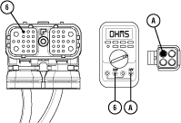
Measure resistance between 38-Way Transmission Harness Connector Pin 6 and 4-Way Diagnostic Connector Pin B. Record reading(s) in table.
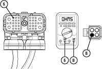
Compare reading(s) in table.
If any reading is out of range, replace Transmission Harness. Go to Step V
If all readings are in range, replace Transmission Electronic Control Unit (TECU). Go to Step V
| Pins | Range | Reading(s) |
|---|---|---|
| 6 to A | Open Circuit (OL) | |
| 6 to B | Open Circuit (OL) |
Key off.
Disconnect 3-Way Range Solenoid Valve Connector.
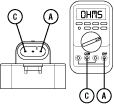
Measure resistance between 3-Way Range Solenoid Valve Pin A and Pin C on the valve body. Record reading(s) in table.
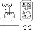
Measure resistance between 3-Way Range Solenoid Valve Pin B and Pin C on the valve body. Record reading(s) in table.
Compare reading(s) in table.
If all readings are in range, replace Transmission Harness. Go to Step V
If any reading is out of range, replace the Range ValveB. Go to Step V
| Pins | Range | Reading(s) |
|---|---|---|
| A to C | 9–16 ohms | |
| B to C | 9–16 ohms |
Key off.
Reconnect all connectors and verify that all components are properly installed.
Connect ServiceRanger.
Key on with engine off.
Retrieve and record the transmission fault codes and FMIs, and their occurrences and timestamps.
If Fault Code 43 is now Inactive, replace Transmission Harness and BRange Valve. Go to Step V
If Fault Code 43 is now Active, replace Transmission Electronic Control Unit (TECU). Go to Step V
Key off.
Set parking brake and chock wheels.
Load test each vehicle battery per OEM specifications. Record reading(s).
If any battery does not pass the Load Test, refer to OEM guidelines for repair or replacement of batteries. Go to Step V
If all batteries pass the Load Test, Go to Step I
| Battery | Voltage Drop | Load Test Status (Pass/Fail) |
|---|---|---|
| 1 | ||
| 2 | ||
| 3 | ||
| 4 | ||
| 5 |
Key off.
Verify TECU battery power and ground supply from the Vehicle Harness is connected properly and not corroded, damaged or loose.
Disconnect 38-Way Vehicle Harness Connector from TECU.
Inspect 38-Way Connector body for damage and bent, spread, corroded or loose terminals.
Load test the Vehicle Power Supply Harness with an external load source. Use a sealed beam headlamp or blower motor attached to Pin 38 (power) and Pin 36 (ground). Load Test for 5 minutes to verify the harness will carry a load with the 30-amp fuse installed.
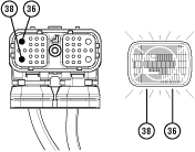
Wiggle the harness during the Load Test from vehicle batteries to TECU.
If issues are found with the power supply or connectors, refer to OEM guidelines for repair or replacement of OEM wiring and continue Load Test.
If the power supply does not carry a load, refer to OEM guidelines for repair or replacement of OEM wiring. Go to Step V
If no issues are found with the power supply or connectors and the power supply carries a load, Go to Step J
Determine which FMI set for Fault Code 43.
If FMI 8 set, replace Transmission Electronic Control Unit (TECU). Go to Step V
If FMI 18 is Inactive, no problem was found. The intermittent nature of the fault makes it likely that the problem is in TECU Power Supply Harness and/or battery/charging system. Contact OEM for further help troubleshooting the wiring and/or battery/charging system. Go to Step V
Key on with engine off.
Connect ServiceRanger.
Go To Programming.
Under "Software Information", record TECU software version.
If TECU software is less than 5570065, update TECU software to 5570065 or greater. Go to Step V
If TECU software is 5570065 or greater, replace the Transmission Electronic Control Unit (TECU). Go to Step V
Key off.
Reconnect all connectors and verify that all components are properly installed.
Key on with engine off.
Clear fault codes using ServiceRanger.
Drive vehicle and attempt to reset the code or duplicate the previous complaint.
Check for fault codes using ServiceRanger.
If no fault codes set Active and vehicle operates properly, test complete.
If Fault Code 43 FMI 3, 4, 5, 6, 8 or 18 sets Active during the test drive, Go to Step A
If Fault Code 43 FMI 12 sets Active during the test drive, contact Eaton at (800) 826-4357.
If a fault code other than 43 sets, troubleshoot per Fault Code Isolation Procedure Index.