J1939 Vehicle Data Link Test
Overview
This symptom driven test is performed if the J1939 Vehicle Data Link is failing to function in some way without setting transmission Fault Code 35. Proper operation of the J1939 Vehicle Data Link is critical for proper transmission operation.
Detection
- Various communication problems between vehicle ECUs.
- ServiceRanger or other diagnostic software may not be able to communicate with TECU or vehicle ECUs.
- If vehicle is configured for the J1939 Start Enable feature the engine may not crank.
Possible Causes
- J1939 Vehicle Data Link
- Wiring shorted to ground, shorted to power or open
- Bent, spread, corroded or loose terminals
- Excessive electrical noise
- Missing or additional terminating resistors
- Various Vehicle ECUs
- Internal Failure
- Loss of Power Supply to ECU
- Poor connection to J1939 Vehicle Data Link
- Wiring shorted to ground, shorted to power or open
Component Identification
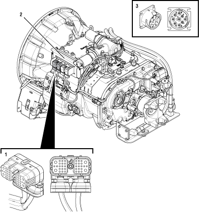 |
1. 38-Way Vehicle Harness Connector 2. Transmission Electronic Control Unit (TECU) 3. 9-Way Diagnostic Connector (in cab) |
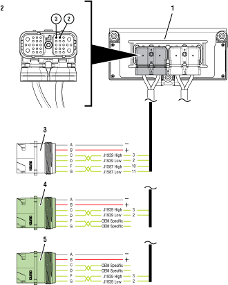 |
1. Transmission Electronic Control Unit (TECU) 2. 38-Way Vehicle Harness Connector 3. 9-Way Diagnostic Connector (Black) - OEM Specific CD (in cab) 4. 9-way Diagnostic Connector (Green) - OEM Specific CD (in cab) 5. 9-way Diagnostic Connector (Green) - OEM Specific FG (in cab) |
 |
J1939 Vehicle Data Link Test
Set parking brake and chock wheels.
Key on with engine off.
Connect ServiceRanger.
Update transmission software to latest available level.
Note: To avoid damaging the TECU, use an approved communications adapter and ensure all satellite systems are disabled before updating software.
Retrieve and record the transmission fault codes and FMIs, and their occurrences and timestamps.
If Fault Code 35 is Active or Inactive, troubleshoot per Fault Code Isolation Procedure Index on page 13.
If another Fault Code is Active, troubleshoot per Fault Code Isolation Procedure Index on page 13.
If Fault Codes 35 is not present and there are no other Active fault codes, Go to Step B
If ServiceRanger does not connect, Go to Step C
Set parking brake and chock wheels.
Place transmission in PD Mode. See more about Product Diagnostic (PD) Mode.
Note: Transmission does not enter PD Mode when Active fault codes exist.
Note: Solid “PD” in display when test is active.

Wiggle wiring and connections through out the entire J1939 Vehicle Data Link up to the 38-Way TECU Vehicle Harness. Look for any obvious signs of rubbing or chafing on any of the wires. Consult OEM for specific wire routing locations.
Exit PD Mode.
If the ServiceRanger connection to the vehicle was lost or Fault Code 35 became Active while wiggling the J1939 Vehicle Data Link, refer to OEM guidelines for repair or replacement of J1939 Vehicle Data Link. Go to Step V
If no fault code set active, Go to Step C
Key off.
Refer to the OEM and identify the TECU location on the J1939 Vehicle Data Link at the 9-Way Diagnostic Connector.
If Black 9-Way Diagnostic Connector, Go to Step D
If Green 9-Way Diagnostic Connector on Pin C and Pin D, Go to Step D
If Green 9-Way Diagnostic Connector on Pin F and Pin H, Go to Step H
Key off.
Measure resistance between 9-Way Diagnostic Connector Pin C and Pin D. Record reading in table.
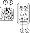
Compare reading(s) in table.
If readings are out of range, refer to OEM guidelines for repair or replacement of J1939 Vehicle Data Link. Go to Step V
If readings are in range, Go to Step E
| Pins | Range | Reading(s) |
|---|---|---|
| C to D | 50–70 Ohms |
Key off.
Disconnect the 38-Way TECU Vehicle Harness Connector.
Inspect the 38-Way TECU Vehicle Harness Connector for contamination, corrosion, damage, loose, bent or spread terminals.
Inspect the TECU side of the 38-Way TECU Vehicle Harness Connector for contamination, corrosion, damage, loose, bent or spread terminals.
If any contamination or damage is found, refer to OEM guidelines for repair or replacement of the 38-Way TECU Vehicle Harness Connector.
If no contamination or damage is found, Go to Step F
Key off.
Measure resistance between 38-Way TECU Vehicle Harness Connector Pin 3 and 9-Way Diagnostic Connector Pin C. Record reading in table.
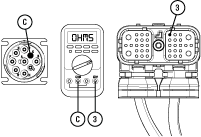
Compare reading(s) in table.
If readings are out of range, refer to OEM guidelines for repair or replacement of J1939 Vehicle Data Link. Go to Step V
If readings are in range, Go to Step G
| Pins | Range | Reading(s) |
|---|---|---|
| 3 to C | 0–0.3 Ohms |
Key off.
Measure resistance between 38-Way TECU Vehicle Harness Connector Pin 2 and 9-Way Diagnostic Connector Pin D. Record reading in table.
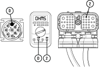
Compare reading(s) in table.
If readings are out of range, refer to OEM guidelines for repair or replacement of J1939 Vehicle Data Link. Go to Step V
If readings are in range, Go to Step L
| Pins | Range | Reading(s) |
|---|---|---|
| 2 to D | 0–0.3 Ohms |
Key off.
Measure resistance between 9-Way Diagnostic Connector Pin F and Pin G. Record reading in table.
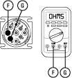
Compare reading(s) in table.
If readings are out of range, refer to OEM guidelines for repair or replacement of J1939 Vehicle Data Link. Go to Step V
If readings are in range, Go to Step I
| Pins | Range | Reading(s) |
|---|---|---|
| F to G | 50–70 Ohms |
Key off.
Disconnect the 38-Way TECU Vehicle Harness Connector.
Inspect the 38-Way TECU Vehicle Harness Connector for contamination, corrosion, damage, loose, bent or spread terminals.
Inspect the TECU side of the 38-Way TECU Harness Connector for contamination, corrosion, damage, loose, bent or spread terminals.
If any contamination or damage is found, refer to OEM guidelines for repair or replacement of the 38-Way TECU Vehicle Harness Connector.
If no contamination or damage is found, Go to Step J
Key off.
Measure resistance between 38-Way TECU Vehicle Harness Connector Pin 3 and 9-Way Diagnostic Connector Pin F. Record reading in table.
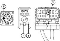
Compare reading(s) in table.
If readings are out of range, refer to OEM guidelines for repair or replacement of J1939 Vehicle Data Link. Go to Step V
If readings are in range, Go to Step K
| Pins | Range | Reading(s) |
|---|---|---|
| 3 to F | 0–0.3 Ohms |
Key off.
Measure resistance between 38-Way TECU Vehicle Harness Connector Pin 2 and 9-Way Diagnostic Connector Pin G. Record reading(s) in table.
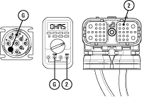
Compare reading(s) in table.
If readings are out of range, refer to OEM guidelines for repair or replacement of J1939 Vehicle Data Link. Go to Step V
If readings are in range, Go to Step L
| Pins | Range | Reading(s) |
|---|---|---|
| 2 to G | 0–0.3 Ohms |
Key off.
Reconnect all connectors and verify that all components are properly installed.
Key on with engine off.
Connect ServiceRanger.
Go To “Data Monitor”.
Select “Components” tab.
Monitor the roster of vehicle ECUs currently communicating on the J1939 Vehicle Data Link.
Compare this list to the roster of vehicle ECUs that should be communicating on the J1939 Vehicle Data Link.
Note: Contact the OEM for information about which vehicle ECUs should be on the J1939 Vehicle Data Link.
If no vehicle ECUs are present on the ServiceRanger roster, Go to Step M
If all vehicle ECUs are present on the ServiceRanger roster, no problem was found during testing. Test complete. Contact the OEM if further diagnostics are required.
If any vehicle ECU is missing from the ServiceRanger roster, investigate that device to verify that it is properly powered and wired to the J1939 Vehicle Data Link. Repair or replace any component or wiring per OEM requirements. Go to Step V
Key on with engine off.
Connect ServiceRanger.
Go To “Data Monitor”.
Select “Components” tab.
Monitor the roster of vehicle ECUs currently communicating on the J1939 Vehicle Data Link.
Individually remove each vehicle ECU from the J1939 Vehicle Data Link.
After removing each device, monitor the ServiceRanger ECU roster.
If the removal of an ECU from the J1939 Vehicle Data Link allows other ECUs to appear in the ServiceRanger ECU roster, the removed ECU may have been shorting out the J1939 Data Link or otherwise preventing communication.
If a problem is found, repair or replace the wiring or component per OEM requirements. Go to Step V
If no problems are found, contact the OEM for further diagnostics.
Key off.
Reconnect all connectors and verify that all components are properly installed.
Key on.
Clear fault codes using ServiceRanger.
Drive vehicle and attempt to reset the code or duplicate the previous complaint.
Check for fault codes using ServiceRanger:
If no fault codes set and vehicle operates properly, test complete.
If Fault Code 35 sets Active during the test drive, Go to Step A
If a fault code other than 35 sets, troubleshoot per Fault Code Isolation Procedure Index.