Fault Code 210: Transmission Oil Pressure (Fluid Pressure Sensor)
J1939: SA 3 SPN 127 FMI 1, 3, 4, 5, 6, 13, 18, 20, 21
Overview
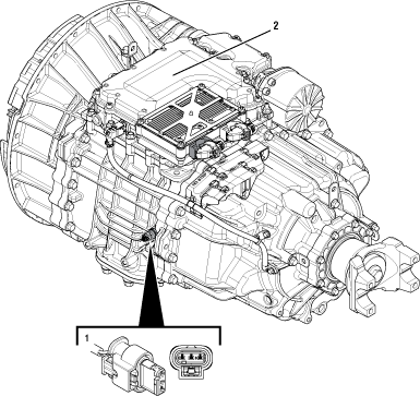
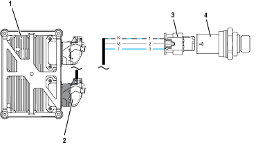
The Endurant HD transmission is equipped with a Fluid Pressure Sensor (FPS) to monitor lubricant oil pressure. The transmission oil pump provides the supply oil for the lubrication system. The FPS taps into the lubrication system and provides a pressure input to the Transmission Control Module (TCM). The TCM monitors the pressure input to verify the transmission is properly filled with oil to lubricate the transmission. The FPS is mounted externally and connected to the TCM at the 20-Way TCM Vehicle Harness Connector.
Detection
The TCM monitors the FPS. If a system failure is detected, the fault is set active.
Conditions to Set Fault Code Active
FMI 1 – Data Valid But Below Normal (Most Severe): FPS reported transmission oil pressure is critically low for 5 seconds.
FMI 3 – Voltage Above Normal or Shorted High: FPS circuit shorted to power for 5 seconds.
FMI 4 – Voltage Below Normal or Shorted Low: FPS circuit shorted to ground for 5 seconds.
FMI 5 – Current Below Normal or Open Circuit: FPS circuit open or shorted to ground for 5 seconds.
FMI 6 – Current Above Normal or Grounded Circuit: FPS reference voltage not between 4.75V to 5.25V for 5 seconds.
FMI 13 – Out Of Calibration: FPS and OEM wiring installed but not configured in the TCM (Service).
FMI 18 – Data Valid But Below Normal Operating Range - Moderately Severe: FPS reported transmission oil pressure is moderately low for 5 seconds.
FMI 20 – Data Drifted High: FPS reporting pressure too high in error when Countershaft is stationary.
FMI 21 – Data Drifted Low: FPS reporting pressure too low in error.
Fallback
FMI 1, 18:
- Amber warning lamp on
- If vehicle is moving
- Red stop lamp on
- Low start gears only
- Upshifts prohibited
- Configurable
FMI 3, 4, 5, 6, 13, 20, 21:
- Amber warning lamp on
- No degraded modes
FMI 18:
- Amber warning lamp on
- No degraded modes
- Configurable
Conditions to Set Fault Code Inactive
FMI 1: FPS oil pressure in range.
FMI 3, 4, 5, 6: FPS in range for 10 seconds.
FMI 13: FPS configured in the TCM.
FMI 18: FPS oil pressure in range for 10 seconds.
Possible Causes
FMI 1, 18:
- Low transmission oil level
- Not properly filled
- Leak
- FPS
- Damaged
- Internal failure
- Internal transmission
- Lubrication system mechanical failure
FMI 3, 4, 5, 6:
- FPS
- Damaged
- Internal failure
- FPS OEM vehicle harness
- Wiring shorted to power, shorted to ground or open
- TCM
- Software issue
- Internal failure
FMI 13:
- FPS not configured in the TCM
- FPS recently installed
- Replacement TCM installed
- Configurable
- Amber warning lamp on
- If vehicle is moving:
- Red stop lamp on
FMI 20:
- FPS OEM vehicle harness
- Wiring shorted to power, shorted to ground or open
- FPS
- Internal failure
FMI 21:
- FPS OEM vehicle harness
- Wiring shorted to power, shorted to ground or open
- FPS
- Internal failure
- Low transmission oil level
- Not properly filled
- Leak
Additional Tools
- Endurant HD Service Manual TRSM0950
- 3-Way Eaton Diagnostic Adapter - RR1060TR
- Digital Volt/Ohm Meter (DVOM)
- Digital Pressure Gauge (or Analog 0-100 psi maximum)
- Oil Pressure Adapter (M14 x 1.5 O-ring Straight Thread)
Component Identification
 |
1. Fluid Pressure Sensor (FPS) 2. Transmission Control Module (TCM) |
 |
1. Transmission Control Module (TCM) 2. 20-Way TCM Vehicle Harness Connector 3. 3-Way Fluid Pressure Sensor Connector 4. Fluid Pressure Sensor (FPS) |
 |
Fault Code 210 Troubleshooting
Set vehicle parking brake and chock wheels.
Record the transmission fault codes, FMIs, occurrences, and timestamps from the Service Activity Report created during the Diagnostic Procedure.
If Fault Code 210 FMI 1, 18 is Active or Inactive, Go to Step B
If Fault Code 210 FMI 3, 4, 5, 6, 20, 21 is Active or Inactive, Go to Step D
If Fault Code 210 FMI 13 is Inactive, the Fluid Pressure Sensor and wiring are installed and configured in the TCM. Test Complete, Go to Step V
If Fault Code 210 FMI 13 is Active, the Fluid Pressure Sensor and wiring were installed but not configured in the TCM. Contact Eaton Cummins Automated Transmission Technologies Cummins Automated Transmission Technologies at 1-800-826-HELP (4357) for further diagnostic instructions. Go to Step V
Key off.
Perform Oil Level Inspection Procedure.
Note: Reference Endurant HD Service Manual TRSM0950, Oil Level Inspection Procedure.
If FMI 1, 18 and transmission oil level is in range, Go to Step F
If FMI 21 and transmission oil level is in range, replace the Fluid Pressure Sensor (FPS). Go to Step V
If FMI 1, 18, 21 and transmission oil level is out of range, Go to Step C
Key off.
Perform Oil Drain Removal.
NoticeNote: Reference Endurant HD Service Manual TRSM0950, Oil Drain Removal Service Procedure.
Record residual oil volume in table.
Remove PTO cover and inspect for damage.
Contact Eaton Cummins Automated Transmission Technologies at 800-826-4357 for further diagnostic instructions. Go to Step V
| Residual Oil Volume |
|---|
Key off.
Disconnect the 3-Way FPS Harness Connector.
Inspect the 3-Way FPS Harness Connector, verify the connector is free from contamination and corrosion; the terminals are not bent, spread or loose; and there is no damage to the connector body.
Connect the 3-Way Eaton Diagnostic Adapter (EDA) to the 3-Way FPS Harness Connector.
Measure resistance between 3-Way EDA Pin 2 (Ground) and Pin 3 (Signal). Record reading in table.

Key on.
Measure voltage at the 3-Way EDA Pin 1 (5V) and Pin 2 (Ground). Record reading in table.

Compare reading(s) in table.
If readings are in range, Go to Step E
If readings are out of range, refer to OEM guidelines for repair or replacement of the FPS signal, power and/or ground circuit(s) between the 3-Way FPS Connector and 20-Way TCM Vehicle Harness Connector. Go to Step V
| Ignition State | Pins | Range | Reading(s) |
|---|---|---|---|
| Key off | 2 to 3 | 3k-9k Ohms | |
| Key on | 1 to 2 | 4.75–5.25 V |
Key off.
Disconnect 20-Way TCM Vehicle Harness Connector.
Inspect the 20-Way TCM Vehicle Harness Connector, verify the connector is free from contamination and corrosion; the terminals are not bent, spread or loose; and there is no damage to the connector body.
Measure resistance between 3-Way EDA Pin 3 (signal) and Ground. Record reading in table.

Compare reading(s) in table.
If FMI 3, 4, 5, 6, 20 and readings are in range, replace the Fluid Pressure Sensor (FPS). Go to Step V
If FMI 21 and readings are in range, Go to Step B
If FMI 3, 4, 5, 6, 20, 21 and readings are out of range, refer to OEM guidelines for repair or replacement of the FPS signal circuit between the 3-Way Fluid Pressure Sensor Connector and 20-Way TCM Vehicle Harness Connector. Go to Step V
| Pins | Range | Reading(s) |
|---|---|---|
| 3 to ground | Open Circuit (OL) |
Key off.
Perform Fluid Pressure Sensor (FPS) Removal.
Install Oil Pressure Adapter (M14x1.5 O-ring Straight Thread) and torque to 19-23 Nm (14-17 lb-ft).
Connect Digital Pressure Gauge (or Analog 0-100 psi maximum) to Oil Pressure Adapter.
Key on with engine running.
Idle engine (650-750 RPM) for 2 minutes to stabilize transmission oil pressure.
With engine idling at 650-750 RPM, monitor pressure gauge and record reading in table.
Increase and hold engine at 950-1050 RPM, monitor pressure gauge and record reading in table.
Increase and hold engine at 1150-1250 RPM, monitor pressure gauge and record reading in table.
Increase and hold engine at 1350-1450 RPM, monitor pressure gauge and record reading in table.
Key off.
Compare reading(s) in table.
If readings are in range, replace the Fluid Pressure Sensor (FPS). Go to Step V
If readings are out of range, Go to Step C
| Engine RPM | Range | Reading(s) |
|---|---|---|
| 650-750 | 5-15 psi | |
| 950-1050 | 10-20 psi | |
| 1150-1250 | 15-25 psi | |
| 1350-1450 | 20-35 psi |
Key off.
Reconnect all connectors and verify that all components are properly installed.
Key on with engine off.
Connect ServiceRanger.
Go to “Fault Codes”.
Select “Clear All Faults”.
Operate vehicle and attempt to reset the fault code or duplicate the previous complaint.
Check for fault codes using ServiceRanger.
If no fault codes set and vehicle operates properly, test complete.
If Fault Code 210 sets Active during operation, Go to Step A
If a fault code other than 210 sets Active, troubleshoot per Fault Code Isolation Procedure Index.