Fault Code 212: Transmission Oil Temperature (Fluid Temperature Sensor)
J1939: SA 3 SPN 177 FMI 0, 2, 4, 5, 6, 10, 15, 16
Overview
The Endurant HD transmission is equipped with a Fluid Temperature Sensor (FTS) to monitor sump oil temperature. Sump oil temperature represents the overall operating temperature of the transmission. The FTS provides a temperature input to the Transmission Control Module (TCM). The FTS is mounted in the Mechatronic Transmission Module (MTM) and connected to the TCM at the 74-way Transmission Harness Connector.
Detection
The TCM monitors the FTS, if a system failure is detected, the fault is set Active.
Conditions to Set Fault Code Active
FMI 0 – Data Valid but Above Normal (Most Severe): Transmission oil temperature greater than 275°F (135°C) for 10 seconds.
FMI 2 – Data Erratic: Transmission oil temperature out of range, greater than 302°F (150°C) or less than -41.8°F (-41°C), for 5 seconds.
FMI 4 - Voltage Below Normal or Shorted Low: FTS circuit shorted to ground for 5 seconds.
FMI 5 - Current Below Normal or Open Circuit: FTS circuit open or shorted to power for 5 seconds.
FMI 6 - Current Above Normal or Shorted Circuit: FTS reference voltage not between 4.75V to 5.25V for 5 seconds.
FMI 10 - Abnormal Rate of Change: Transmission Oil Temperature rate of change greater than 20°F (11°C) per second.
FMI 15 - Data Valid but Above Normal (Least Severe): Transmission oil temperature greater than 252°F (122°C) for 15 minutes or above 273°F (134°C) for 1 minute.
FMI 16 - Data Valid but Above Normal (Moderately Severe): Transmission oil temperature greater than 252°F (122°C) for 30 minutes or above 273°F (134°C) for 2 minutes.
Fallback
FMI 0, 15, 16
- Amber warning lamp on (OEM specific)
- Red stop lamp on (OEM specific)
- Shift performance may be degraded
FMI 2, 4, 5, 6, 10
- Amber warning lamp on (OEM specific)
- No degraded modes
Conditions to Set Fault Code Inactive
FMI 0, 15, 16: Transmission oil temperature below 252°F (122° C) for 1 minute.
FMI 2: Transmission oil temperature in range for 10 seconds.
FMI 4: FTS circuit not shorted to ground for 10 seconds.
FMI 5: FTS circuit not open or shorted to power for 10 seconds.
FMI 6: FTS reference voltage in range for 10 seconds.
FMI 10: Key cycle and fault condition no longer exist.
Possible Causes
FMI 0, 15, 16:
- Maximum vehicle Gross Combination Weight (GCW) and/or operating grade exceeded
- Low transmission oil level
- Not properly filled
- Leak
- FTS not configured in the TCM
- Replacement TCM installed
- FTS
- Internal failure
- Internal transmission
- Lubrication system mechanical failure
FMI 2, 4, 5, 6, 10:
- MTM
- FTS Internal Failure
- Harness wiring shorted to power, shorted to ground or open
- TCM
- Internal failure
Additional Tools
- Endurant HD Service Manual TRSM0950
- Digital Volt/Ohm Meter (DVOM)
Fault Code 212 Troubleshooting
Set vehicle parking brake and chock wheels.
Record the transmission fault codes, FMIs, occur-rences, and timestamps from the Service Activity Report created during the Diagnostic Procedure.
If Fault Code 212 FMI 0, 15, 16 is Active or Inactive, Go to Step B
If Fault Code 212 FMI 2, 4, 5, 6, 10 is Active or Inactive, Go to Step D
Key off.
Perform Oil Level Inspection Procedure.
Note: Reference Endurant HD Service Manual TRSM0950, Oil Level Inspection Procedure.
If FMI 0, 15, 16 and transmission oil level is in range, FTS reported a higher than expected oil sump temperature. Based on transmission model, verify maximum vehicle Gross Combination Weight (GCW) and operating grade is not exceeded. Go to Step V
If FMI 0,15,16 and transmission oil level is out of range, Go to Step C
| Trans Model | Max GCW | Max Grade |
|---|---|---|
| EHD-xxF112C-V | 70,000 lbs (32 Metric Tons) | 21% |
Key off.
Perform Oil Drain Removal.
Note: Place a suitable container under the Oil Drain Plug.
Note: Reference Endurant HD Service Manual TRSM0950, Oil Drain Removal Service Procedure.
Record residual oil volume in table.
Remove PTO cover and inspect for damage.
Contact Eaton Cummins Automated Transmission Technologies at +1 800-826-4357 for further diagnostic instructions. Go to Step V
| Residual Oil Volume |
|---|
Key off.
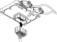
Remove the TCM from the MTM with the 20-Way TCM Vehicle Harness Connector and 20-Way TCM Body Harness Connector connected.

Inspect the TCM side of the 74-Way Transmission Harness Connector, verify the connector is free from contamination and corrosion; the terminals are not bent, spread or loose; and there is no damage to the connector body.
Inspect the TCM Seal, verify the seal is properly installed and there is no damage to the seal.
Note: MTM removal and installation requires the transmission to be removed from the vehicle. Reference Endurant HD Service Manual TRSM0950, Transmission Removal Service Procedure.
If contamination or damage is found to the TCM side of the 74-Way Transmission Harness Connector, replace the Transmission Control Module (TCM) and Mechatronic Transmission Module (MTM). Go to Step V
If no contamination or damage is found, Go to Step E
Key off.
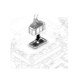
Connect the Eaton Breakout Box with 74-Way Eaton Diagnostic Adapter to the TCM side of the 74-Way Transmission Harness Connector.

Key on.
Measure voltage at the Eaton Breakout Box between Pin 33 and Pin 43. Record reading in table.

Compare reading(s) in table.
Note: MTM removal and installation requires the transmission to be removed from the vehicle. Reference Endurant HD Service Manual TRSM0950, Transmission Removal Service Procedure.
If readings are in range, Go to Step F
If readings are out of range, replace Transmission Control Module (TCM). Go to Step V
| Ignition State | Pins | Range | Reading(s) |
|---|---|---|---|
| Key on | 33 to 43 | 4.75–5.25 V |
Key off.
Connect the Eaton Breakout Box with 74-Way Eaton Diagnostic Adapter to the MTM side of the 74-Way Transmission Harness Connector.

Measure resistance at the Eaton Breakout Box between Pin 33 and Ground (TCM mounting stud). Record reading in table.

If readings are in range, Go to Step G
If readings are out of range, replace Mechatronic Transmission Module (MTM). Go to Step V
Note: MTM removal and installation requires the transmission to be removed from the vehicle. Reference Endurant HD Service Manual TRSM0950, Transmission Removal Service Procedure.
| Pins | Range | Reading(s) |
|---|---|---|
| 33 to Ground (TCM mounting stud) | Open Circuit (OL) |
Key off.
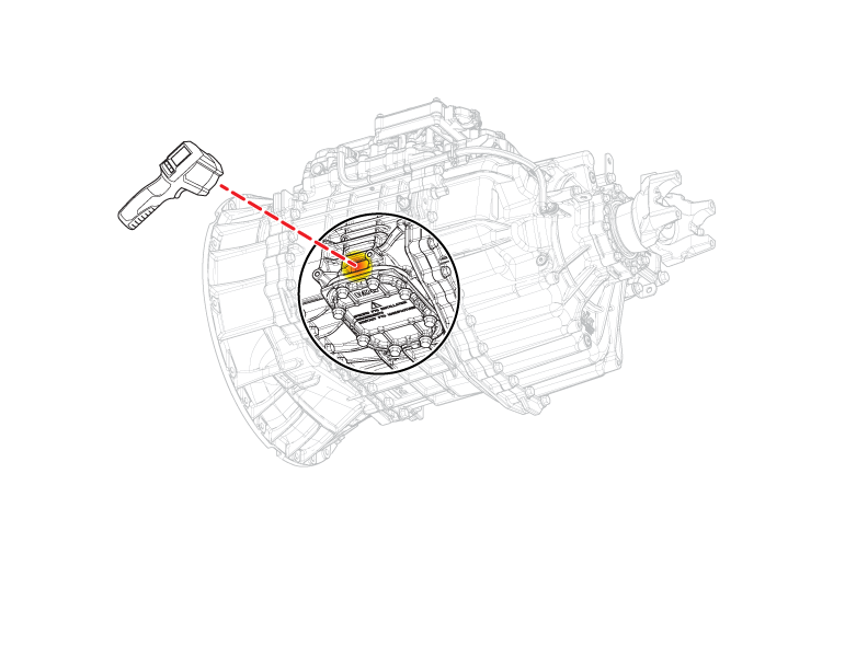
Use Non-contact (infrared) temperature gun to measure main case temperature in area indicated. Record reading in table.

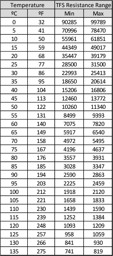
Use Temperature/TFS Resistance Range chart to determine expected FTS resistance range based on the Main Case Temperature. Record Resistance Range in table.

Measure resistance at the Eaton Breakout Box between Pin 33 and Pin 43. Record reading in table.

If readings are in range, Go to Step H
If readings are out of range, replace Mechatronic Transmission Module (MTM). Go to Step V
Note: MTM removal and installation requires the transmission to be removed from the vehicle. Reference Endurant HD Service Manual TRSM0950, Transmission Removal Service Procedure.
| Main Case Temperature | TFS Resistance Range | Pins | Reading(s) |
|---|---|---|---|
| 33 to 43 |
Key off.
Remove the 74-Way Eaton Diagnostic Adapter.
Reinstall the TCM to the MTM.
Reconnect all connectors and verify that all components are properly installed.
Key on.
Connect ServiceRanger.
Retrieve and record transmission fault codes, FMIs, occurrences, and timestamps.
If Fault Code 212 FMI 2, 4, 5, 6, 10 is Active, replace Transmission Control Module (TCM). Go to Step V
If Fault Code 212 FMI 2, 4, 5, 6, 10 is Inactive replace Mechatronic Transmission Module (MTM). Go to Step V
Note: MTM removal and installation requires the transmission to be removed from the vehicle. Reference Endurant HD Service Manual TRSM0950, Transmission Removal Service Main Case Procedure.
Key off.
Reconnect all connectors and verify that all components are properly installed.
Key on with engine off.
Connect ServiceRanger.
Go to "Fault Codes".
Select "Clear All Faults".
Operate vehicle and attempt to set the fault code or duplicate the previous complaint.
Check for fault codes using ServiceRanger:
If no codes set and the vehicle operates properly, test complete.
If Fault Code 212 sets Active during operation, Go to Step A
If a fault code other than 212 sets Active, troubleshoot per Fault Code Isolation Procedure Index on page 13.