Fault Code 115: Primary Data Link (J1939A)
J1939: SA 3 SPN 639 FMI 2, 8, 9, 14, 19, 31
Overview
The Transmission Control Module (TCM) communicates with other vehicle Electronic Control Units (ECUs) over the vehicle J1939 data link. The TCM uses two vehicle J1939 data links to send and receive messages: the Primary Data Link (J1939A) and the Secondary Data Link (J1939B).
The Primary Data Link is used by the TCM to send and receive messages to and from the Engine ECU, Anti-Lock Brake ECU and other vehicle ECUs to complete transmission shift operations. The Secondary Data Link is used in the event that the Primary Data Link is inoperative.
The Primary Data Link (J1939A) is connected to the TCM at the 20-Way TCM Vehicle Harness Connector. The Secondary Data Link (J1939B) is connected to the TCM at the 20-Way TCM Body Harness Connector.
Detection
The TCM monitors vehicle and Engine ECU broadcast messages. If messages are not received or are invalid, the fault is set Active.
Conditions to Set Fault Code Active
FMI 2 – Data Erratic: Primary Data Link (J1939A) vehicle ECU(s) messages not received for 1 second.
FMI 8 – Abnormal Frequency: Primary Data Link (J1939A) Engine ECU messages not received for 1 second while the TCM is receiving messages from other vehicle ECU(s).
FMI 9 – Abnormal Update Rate: Primary Data Link (J1939A) vehicle messages not received for 5 seconds.
FMI 14 – Special Instructions: Primary Data Link (J1939A) Engine ECU messages not received for 5 seconds while the TCM is receiving messages from other vehicle ECU(s).
FMI 19 – Received Network Data In Error: Primary Data Link (J1939A) vehicle ECU(s) messages received but in error.
FMI 31 – Condition Exists: Primary Data Link (J1939A) receiving a vehicle ECU(s) “Stop Start Broadcast” message.
Fallback
FMI 2, 8, 19:
- Amber warning lamp on
- No degraded modes
FMI 9, 14:
- Amber warning lamp on
- If vehicle is configured for J1939 Start Enable feature, engine may not crank
- If vehicle is moving and transmission is in a gear higher than the lowest available start gear:
- Coast Mode and Neutral Coast prohibited
- Urge to Move and Creep Mode prohibited
- Inertia Brake activation prohibited
- Upshifts prohibited
- Clutch engagements prohibited
- Non-Neutral modes prohibited
- PTO mode prohibited
- Hill Start Aid prohibited
- If vehicle is moving and transmission is in a gear higher than the lowest available start gear and Secondary Data Link (J1939B) is not available:
- Red stop lamp on
- Clutch engagements prohibited, vehicle may coast to a stop
- Transmission downshifts to lowest available start gear
FMI 31:
- Amber warning lamp on
- If vehicle is configured for J1939 Start Enable feature, engine may not crank
- Lowest available start gear only
- Coast Mode and Neutral Coast prohibited
- Urge to Move and Creep Mode prohibited
- Inertia Brake activation prohibited
- Upshifts prohibited
- Clutch disengagements prohibited
- Non-Neutral modes prohibited
- PTO mode prohibited
- Hill Start Aid prohibited
Conditions to Set Fault Code Inactive
FMI 2: Primary Data Link (J1939A) vehicle ECU(s) messages received and valid for 20 seconds.
FMI 8: Primary Data Link (J1939A) Engine ECU messages received and valid for 20 seconds.
FMI 9: Primary Data Link (J1939A) vehicle ECU(s) messages received and valid for 10 seconds.
FMI 14: Primary Data Link (J1939A) Engine ECU messages received and valid for 10 seconds.
FMI 19: Key cycle and fault condition no longer exist.
FMI 31: Fault condition no longer exists.
Possible Causes
FMI 2, 9:
- Vehicle Components
- Other vehicle ECU(s) faulted
- Vehicle Harness - Primary Data Link (J1939A)
- Wiring shorted to power, shorted to ground or open
- Terminals bent, spread, corroded, or loose
- Excessive electrical noise
- Missing or additional terminating resistors
FMI 8, 14:
- Vehicle Components
- Engine ECU internal failure
- Engine ECU not powering up
- Vehicle Harness - Primary Data Link (J1939A) between Engine ECU and TCM
- Wiring shorted to power, shorted to ground or open
- Terminals bent, spread, corroded, or loose
- Excessive electrical noise
- Missing or additional terminating resistors
FMI 19:
- Other Vehicle ECU(s)
- Internal failure
FMI 31:
- Other Vehicle ECU(s)
- Informational only, indicates a Vehicle ECU experienced a programming event.
Note: Refer to OEM for troubleshooting a failed system.
Additional Tools
- Endurant XD Service Manual TRSM0960
- Digital Volt Ohm Meter (DVOM)
Component Identification
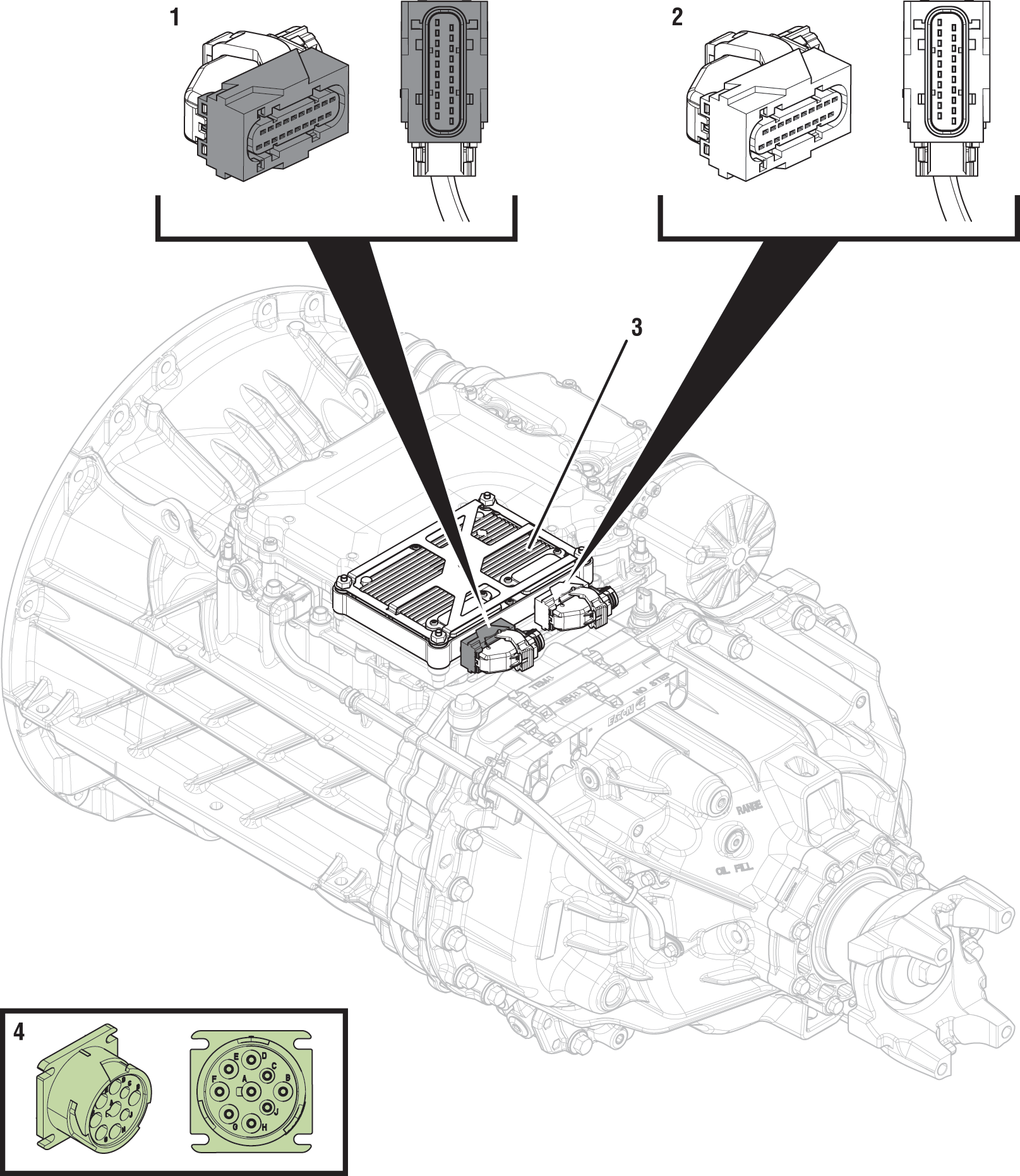 |
1. 20-Way TCM Vehicle Harness Connector 2. 20-Way TCM Body Harness Connector 3. Transmission Control Module (TCM) 4. 9-Way Type 2 Diagnostic Connector (In Cab) |
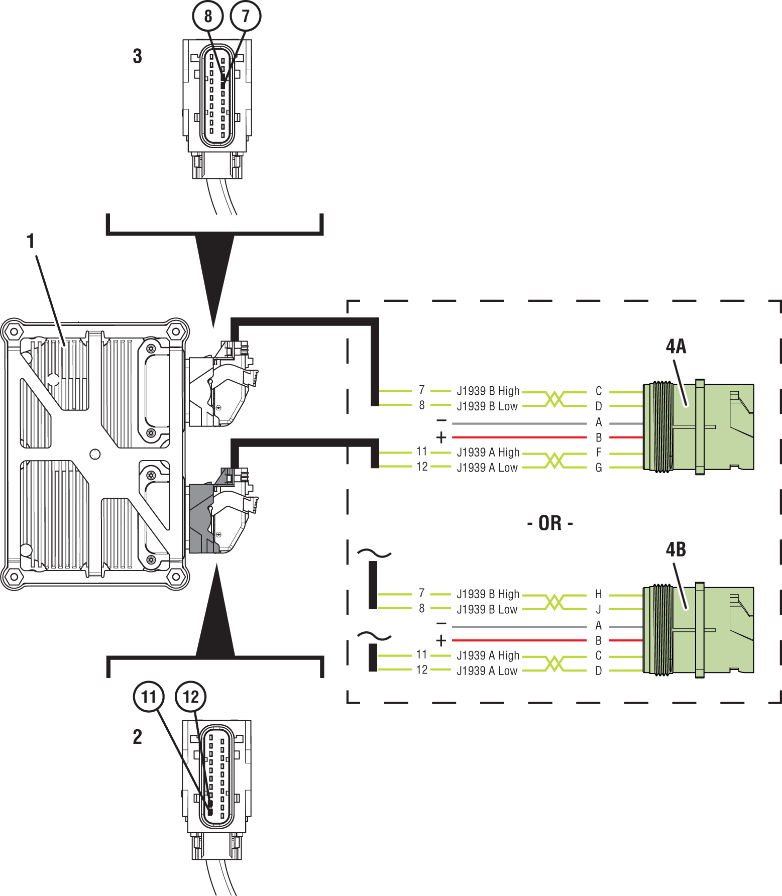 |
1. Transmission Control Module (TCM) 2. 20-Way TCM Vehicle Harness Connector 3. 20-Way TCM Body Harness Connector 4A. 9-Way Type 2 Diagnostic Connector (OEM-Specific Primary Data Link FG) 4B. 9-Way Type 2 Diagnostic Connector (OEM-Specific Primary Data Link CD) |
 |
Fault Code 115 Troubleshooting
Set vehicle parking brake and chock wheels.
Record transmission fault codes, FMIs, occurrences, and timestamps from Service Activity Report created during the Diagnostic Procedure.
If Fault Code 115 is Inactive and there are other Active vehicle or transmission fault codes, troubleshoot all Active fault codes first. Go to Step V
If Fault Code 115 FMI 2, 9 is Active or Inactive, Go to Step B
If Fault Code 115 FMI 14 is Active, Go to Step N
Note: If ServiceRanger connects to TCM, vehicle data link is currently functional between vehicle 9-Way Diagnostic Connector and TCM. Refer to OEM guidelines for Engine ECU and vehicle data link diagnostic instructions.
If Fault Code 115 FMI 14 is Inactive, there may be an intermittent wiring problem in the vehicle Primary Data Link (J1939A) to the Engine ECU, an Engine ECU message fault may exist, and/or the Engine ECU may intermittently not be powering up. Refer to OEM guidelines for repair or replacement of vehicle Primary Data Link (J1939A) or Engine ECU. Go to Step V
If Fault Code 115 FMI 19 is Active or Inactive, a fault condition exists on the Primary Data Link (J1939A) with the Engine ECU or another Vehicle ECU(s). Contact OEM for further diagnostic instructions. Go to Step V
If Fault Code 115 FMI 31 is Inactive or Active, this indicates a vehicle ECU experienced a programming event (Informational only). Go to Step V
Key off.
Disconnect 20-Way TCM Body Harness Connector from TCM.
Key on with engine off.
Connect ServiceRanger.
Go To “Fault Codes”.
Retrieve and record transmission fault codes, FMIs, occurrences, and timestamps.
If Fault Code 115 is Inactive, a wiring problem exists in the vehicle Secondary Data Link (J1939B). Refer to OEM guidelines for repair or replacement of the vehicle Secondary Data Link (J1939B) harness and/or 20-Way TCM Vehicle Harness Connector. Go to Step V
If Fault Code 115 was Inactive or remains Active, key off and reconnect 20-Way TCM Body Harness Connector. Go to Step C
Key off.
Refer to OEM to identify TCM J1939 pin locations on vehicle 9-Way J1939 Diagnostic Connector.
If TCM is on Pins C and D, Go to Step I
If TCM is on Pins F and G, Go to Step D
Key on with engine off.
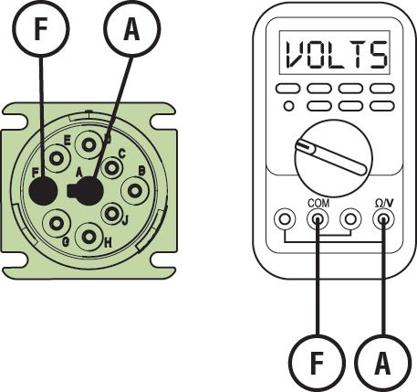
Measure voltage between 9-Way Diagnostic Connector Pin F and Pin A. Record reading in table.
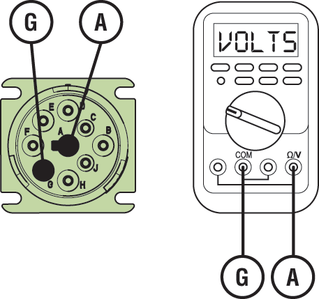
Measure voltage between 9-Way Diagnostic Connector Pin G and Pin A. Record reading in table.
Record Total Voltage in table by adding voltage readings together.
Compare reading(s) in table.
If readings are in range, Go to Step E
If readings are out of range, refer to OEM guidelines for repair or replacement of vehicle Primary Data Link (J1939A). Go to Step V
| Pins | Range | Reading(s) |
|---|---|---|
| F to A | N/A | |
| G to A | N/A | + |
| Total Voltage | 4.5–5.5 V | = |
Key off.
Measure resistance between 9-Way Diagnostic Connector Pin F and Pin G. Record reading in table.
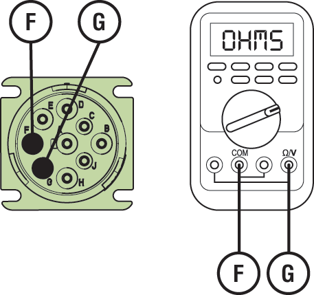
Compare reading(s) in table.
If readings are out of range, refer to OEM guidelines for repair or replacement of vehicle Primary Data Link (J1939A). Go to Step V
If readings are in range, Go to Step F
| Pins | Range | Reading(s) |
|---|---|---|
| F to G | 50–70 Ohms |
Key off.
Disconnect 20-Way TCM Vehicle Harness Connector from TCM.
Inspect 20-Way TCM Vehicle Harness Connector, verify connector is free from contamination and corrosion; terminals are not bent, spread or loose; and there is no damage to connector body.
Inspect 20-Way TCM Vehicle Connector, verify connector is free from contamination and corrosion; terminals are not bent, spread or loose; and there is no damage to connector body.
If contamination or damage is found, refer to OEM guidelines for repair or replacement of 20-Way TCM Vehicle Harness Connector. Go to Step V
If no contamination or damage is found, Go to Step G
Key off.
Measure resistance between 20-Way TCM Vehicle Harness Connector Pin 11 and Pin 12. Record reading in table.
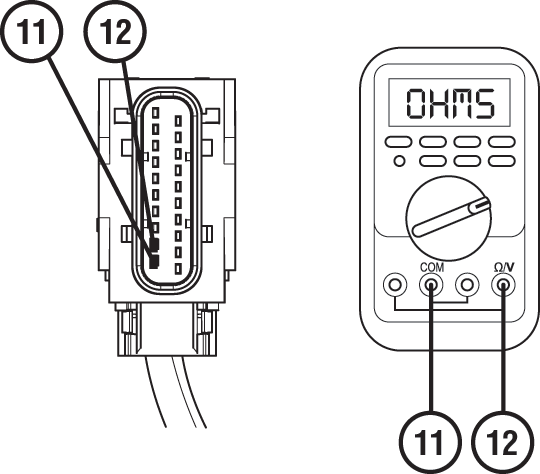
Compare reading(s) in table.
If readings are out of range, refer to OEM guidelines for repair or replacement of vehicle Primary Data Link (J1939A). Go to Step V
If readings are in range, Go to Step H
| Pins | Range | Reading(s) |
|---|---|---|
| 11 to 12 | 50–70 Ohms |
Key off.
Reconnect all connectors and verify all components are properly installed.
Key on with engine off.
Connect ServiceRanger.
Go To “Fault Codes”.
Retrieve and record transmission fault codes, FMIs, occurrences, and timestamps.
If Fault Code 115 is Inactive, an intermittent wiring problem exists in the vehicle Primary Data Link (J1939A). Refer to OEM guidelines for repair or replacement of vehicle Primary Data Link (J1939A) harness and/or 20-Way TCM Vehicle Harness Connector. Go to Step V
If Fault Code 115 is Active and no fault was found with the vehicle Primary Data Link (J1939A), replace Transmission Control Module (TCM). Go to Step V
Note: If troubleshooting indicates no fault found in wiring or connections to TCM, ensure an intermittent issue does not exist in wiring or connections before replacing TCM.
Key on with engine off.
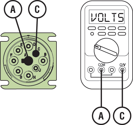
Measure voltage between 9-Way Diagnostic Connector Pin C and Pin A. Record reading in table.
Measure voltage between 9-Way Diagnostic Connector Pin D and Pin A. Record reading in table.
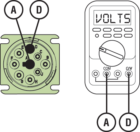
Record Total Voltage in table by adding voltage readings together.
Compare reading(s) in table.
If readings are in range, Go to Step J
If readings are out of range, refer to OEM guidelines for repair or replacement of vehicle Primary Data Link (J1939A). Go to Step V
| Pins | Range | Reading(s) |
|---|---|---|
| C to A | N/A | |
| D to A | N/A | + |
| Total Voltage | 4.5–5.5 V | = |
Key off.
Measure resistance between 9-Way Diagnostic Connector Pin C and Pin D. Record reading in table.
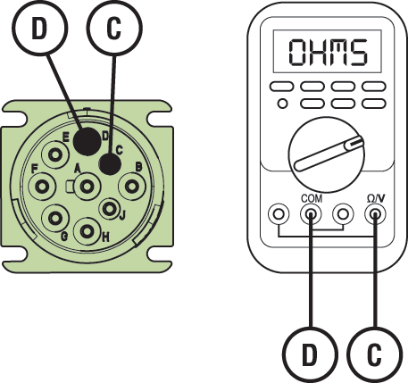
Compare reading(s) in table.
If readings are out of range, refer to OEM guidelines for repair or replacement of vehicle Primary Data Link (J1939A). Go to Step V
If readings are in range, Go to Step K
| Pins | Range | Reading(s) |
|---|---|---|
| C to D | 50–70 Ohms |
Key off.
Disconnect 20-Way TCM Vehicle Harness Connector from TCM.
Inspect 20-Way TCM Vehicle Harness Connector, verify connector is free from contamination and corrosion; terminals are not bent, spread or loose; and there is no damage to connector body.
Inspect 20-Way TCM Vehicle Connector, verify connector is free from contamination and corrosion; terminals are not bent, spread or loose; and there is no damage to connector body.
If contamination or damage is found, refer to OEM guidelines for repair or replacement of 20-Way TCM Vehicle Harness Connector. Go to Step V
If no contamination or damage is found, Go to Step L
Key off.
Measure resistance between 20-Way TCM Vehicle Harness Connector Pin 11 and Pin 12. Record reading in table.

Compare reading(s) in table.
If readings are out of range, refer to OEM guidelines for repair or replacement of vehicle Primary Data Link (J1939A). Go to Step V
If readings are in range, Go to Step M
| Pins | Range | Reading(s) |
|---|---|---|
| 11 to 12 | 50–70 Ohms |
Key off.
Reconnect all connectors and verify all components are properly installed.
Key on with engine off.
Connect ServiceRanger.
Go To “Fault Codes”.
Retrieve and record transmission fault codes, FMIs, occurrences, and timestamps.
If Fault Code 115 is Inactive, an intermittent wiring problem exists in the vehicle Primary Data Link (J1939A). Refer to OEM guidelines for repair or replacement of vehicle Primary Data Link (J1939A) harness and/or 20-Way TCM Vehicle Harness Connector. Go to Step V
If Fault Code 115 is Active and no fault was found with the vehicle Primary Data Link (J1939A), replace Transmission Control Module (TCM). Go to Step V
Note: If troubleshooting indicates no fault found in wiring or connections to TCM, ensure an intermittent issue does not exist in wiring or connections before replacing TCM.
Key off.
Locate and disconnect Engine ECU vehicle harness connector containing vehicle Primary Data Link (J1939A).
Note: Refer to OEM guidelines for Engine ECU vehicle harness connector location, connector removal, and J1939 High (+) and J1939 Low (-) connector pin locations.
Measure resistance between Engine ECU vehicle harness connector Pin J1939 High (+) and Pin J1939 Low (-). Record reading in table.
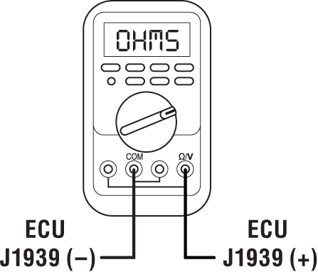
Compare reading(s) in table.
If readings are out of range, refer to OEM guidelines for repair or replacement of vehicle Primary Data Link (J1939A). Go to Step V
If readings are in range, Engine ECU has continuity to the vehicle Primary Data Link (J1939A). The intermittent nature of the fault makes it likely one of the following conditions exists: an Engine ECU message fault exists and/or the Engine ECU may intermittently not be powering up. Contact OEM for further diagnostic instructions. Go to Step V
| Pins | Range | Reading(s) |
|---|---|---|
| J1939 High (+) to J1939 Low (-) | 50–70 Ohms |
Key off.
Reconnect all connectors and verify all components are properly installed.
Key on with engine off.
Connect ServiceRanger.
Go To “Fault Codes”.
Select “Clear All Faults”.
Operate vehicle and attempt to reset the fault code or duplicate the previous complaint.
Check for fault codes using ServiceRanger.
If no fault codes set and vehicle operates properly, test complete.
If Fault Code 115 sets Active, Go to Step A
If a fault code other than 115 sets Active, troubleshoot per the Fault Code Isolation Procedure Index