Fault Code 120: Start Enable Relay
J1939: SA 3 SPN 1321 FMI 3, 4, 5, 7, 12
Overview
The Transmission Control Module (TCM) disables engine cranking when the transmission is in a non-Neutral gear position. The TCM configuration parameter "Start Enable Type" is set to one of two different options depending on the method used on the vehicle. One method uses the TCM and a normally-open Start Enable Relay (SER) to interrupt power to the engine Starter. The second method relies on the TCM to send a Transmission Engine Crank Enable message to the Engine ECU over the vehicle Primary Data Link (J1939A) when engine cranking is allowed. The SER and Primary Data Link (J1939A) wiring connect to the TCM through the 20-Way TCM Vehicle Harness Connector.
Detection
The TCM monitors the SER control circuits. If a system failure is detected, the fault is set Active.
Note: This fault code will not set on vehicles that use the Transmission Engine Crank Enable message on the Primary Data Link (J1939A).
Conditions to Set Fault Code Active
FMI 3 – Voltage Above Normal or Shorted High: SER circuit shorted to power for 1 second.
FMI 4 – Voltage Below Normal or Shorted Low: SER circuit shorted to ground for 1 second.
FMI 5 – Current Below Normal or Open Circuit: SER circuit open for 1 second.
FMI 7 – Mechanical System Not Responding: Engine cranked when SER was not energized by the TCM for 2 seconds.
FMI 12 – Bad Intelligent Device: SER enabled under inappropriate conditions.
Fallback
FMI 3, 4, 5, 7:
- Amber Warning lamp on
- No degraded modes
FMI 12:
- Engine cranking prohibited
Conditions to Set Fault Code Inactive
FMI 3: SER circuit not shorted to power for 10 seconds.
FMI 4: SER circuit not shorted to ground for 10 seconds.
FMI 5: SER circuit not open for 10 seconds.
FMI 7: SER wiring issue corrected and ignition key cycle.
FMI 12: Key cycle and fault condition no longer exist.
Possible Causes
FMI 3, 4, 5, 7:
- Vehicle Components
- SER internal failure
- Vehicle Harness - SER Circuit
- Wiring shorted to power, shorted to ground or open
- Terminals bent, spread, corroded, or loose
- TCM
- “Start Enable Type” incorrectly configured as “Relay” on vehicle equipped with a “J1939” start enable system.
FMI 12:
- TCM
- Internal failure
- Software issue
Note: Refer to OEM for troubleshooting a failed system.
Additional Tools
- Endurant XD Service Manual TRSM0960
- Digital Volt Ohm Meter (DVOM)
Component Identification
 |
1. 20-Way TCM Vehicle Harness Connector 2. Transmission Control Module (TCM) 3. 5-Way Start Enable Relay Socket |
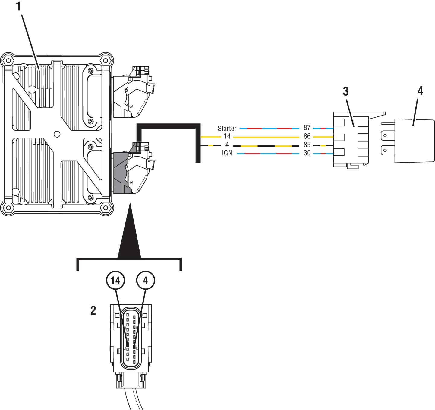 |
1. Transmission Control Module (TCM) 2. 20-Way TCM Vehicle Harness Connector 3. 5-Way Start Enable Relay Socket 4. 5-Way Start Enable Relay |
 |
 |
Start Enable Relay Circuit States (Normally Open) 1. Open Relay - Key On and Transmission is Unable to Confirm Neutral 2. Open Relay - Key Start and Transmission is Unable to Confirm Neutral 3. Closed Relay - Key On and Transmission Confirmed in Neutral 4. Closed Relay - Key Start and Transmission Confirmed in Neutral |
 |
Fault Code 120 Troubleshooting
Set vehicle parking brake and chock wheels.
Record transmission fault codes, FMIs, occurrences, and timestamps from Service Activity Report created during the Diagnostic Procedure.
Note: If Fault Code 120 is inactive and engine cranks, but does not run, refer to OEM for troubleshooting a failed system.
Note: Some OEMs and chassis may use an alternate wiring pattern, which may include the use of second relay for other vehicle systems. Consult OEM wiring diagrams.
If Fault Code 120 is Inactive and there are other Active vehicle or transmission fault codes, troubleshoot all Active fault codes. Go to Step V
If Fault Code 120 FMI 3, 4, 5 is Active or Inactive, Go to Step B
If Fault Code 120 FMI 7 is Active or Inactive, Go to Step K
If Fault Code 120 FMI 12 is Active or Inactive, Contact Eaton Cummins Automated Transmission Technologies for further diagnostic instructions. For Help Line phone numbers, go to Contact Information. Go to Step V
Key off.
Allow TCM to perform a complete power down.
Key on with engine off.
Connect ServiceRanger.
Go to “Configuration”.
Select “Vehicle”.
Record “Start Enable Type” Current Value in table.
Record start enable type installed on vehicle in table.
Note: Vehicle's start enable type (Start Enable Relay or J1939) is determined by OEM. Refer to OEM regarding the start enable type installed on vehicle.
Compare reading(s) in table.
If “Start Enable Type” is not configured correctly, select correct configuration option from “New Value” drop down list, select “Apply” and follow on screen prompts. Go to Step V
If FMI 3, 4 or 5 is Active and “Start Enable Type” is configured correctly, Go to Step C
| Location | Start Enable Type |
|---|---|
| TCM (ServiceRanger) | |
| Vehicle |
Key off.
Remove SER from 4-Way relay socket.
Inspect SER and 4-Way relay socket, verify SER socket is not damaged, is free from contamination and corrosion, and terminals are not bent, spread or loose.
If contamination or damage is found, refer to OEM guidelines for repair or replacement of SER and/or 4-Way relay socket. Go to Step V
If no contamination or damage is found, Go to Step D
Key off.
Remove SER.
Inspect SER and connector body for damage, bent, spread, corroded or loose terminals.
Key on with engine off.
Measure voltage between SER socket Pin 86 and Pin 85. Record reading in table.
Note: SER types may vary, refer to OEM wiring diagrams and connector views.
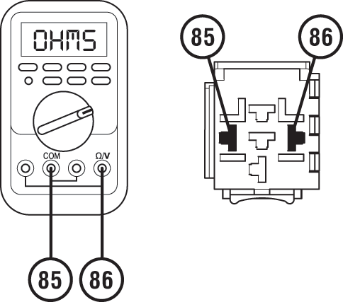
Compare reading(s) in table.
If readings are in range, Go to Step E
If readings are out of range, Go to Step G
| Pins | Range | Reading(s) |
|---|---|---|
| 85 to 86 | 11–13 V |
Key off.
Measure resistance across the SER Pin 85 and Pin 86. Record reading in table.
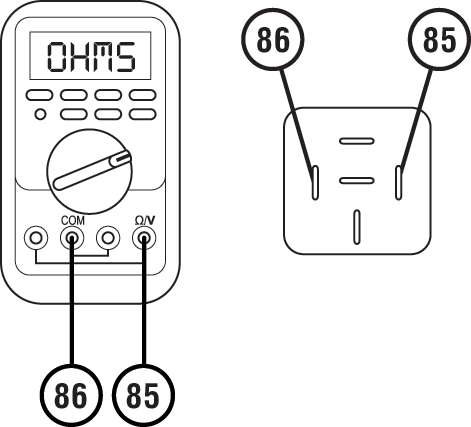
Compare reading(s) in table.
If readings are in range, Go to Step F
If readings are out of range, refer to OEM guidelines for SER replacement. Go to Step V
| Pins | Range | Reading(s) |
|---|---|---|
| 85 to 86 | 40–200 ohms |
Key off.
Disconnect 20-Way TCM Vehicle Harness Connector from TCM.
Inspect 20-Way TCM Vehicle Harness Connector, verify connector is free from contamination and corrosion; terminals are not bent, spread or loose; and there is no damage to connector body.
Inspect 20-Way TCM Vehicle Connector, verify connector is free from contamination and corrosion; terminals are not bent, spread or loose; and there is no damage to connector body.
If contamination or damage is found, refer to OEM guidelines for repair or replacement of 20-Way TCM Vehicle Harness Connector. Go to Step V
If no contamination or damage is found, Go to Step G
Key off.
Measure resistance between 20-Way TCM Vehicle Harness Connector Pin 14 and SER socket Pin 86. Record reading in table.
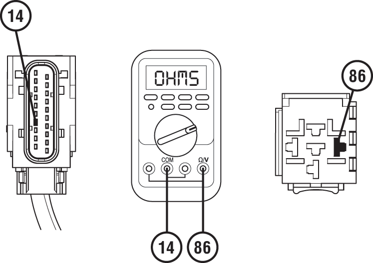
Measure resistance between 20-Way TCM Vehicle Harness Connector Pin 4 and SER socket Pin 85. Record reading in table.
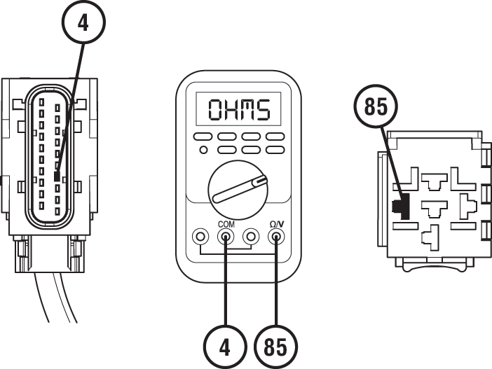
Measure resistance between SER socket Pin 85 and Pin 86. Record reading in table.

Compare reading(s) in table.
If readings are out of range, refer to OEM guidelines for repair or replacement of vehicle harness to 20-Way TCM Vehicle Harness Connector. Go to Step V
If readings are in range, Go to Step H
| Pins | Range | Reading(s) |
|---|---|---|
| 14 to 86 | 0.0–0.3 Ohms | |
| 4 to 85 | 0.0–0.3 Ohms | |
| 85 to 86 | Open Circuit (OL) |
Key off.
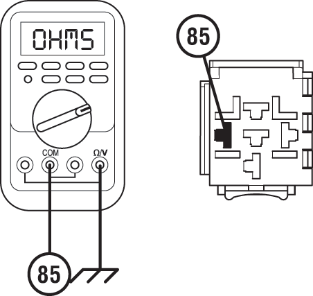
Measure resistance between SER socket Pin 85 and Ground. Record reading.
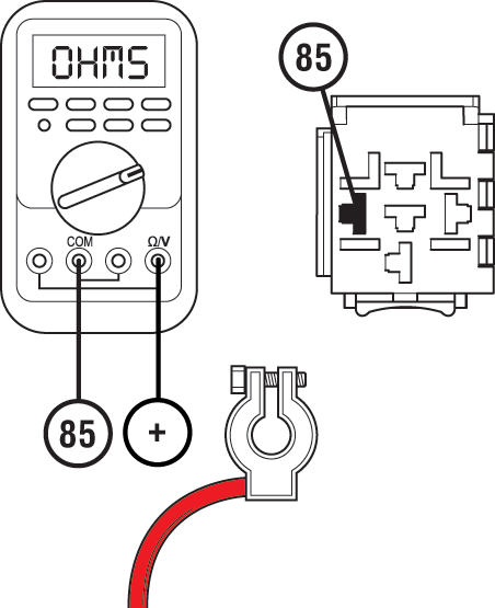
Measure resistance between SER socket Pin 85 and Battery Positive. Record reading.
Compare reading(s) in table.
If readings are out of range, refer to OEM guidelines for repair or replacement of vehicle harness to 20-Way TCM Vehicle Harness Connector. Go to Step V
If readings are in range, Go to Step I
| Pins | Range | Reading(s) |
|---|---|---|
| 85 to Ground | Open Circuit (OL) | |
| 85 to Battery Positive (+) | Open Circuit (OL) |
Key off.
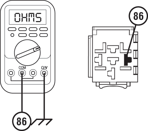
Measure resistance between SER socket Pin 86 and Ground. Record reading in table.
Measure resistance between SER socket Pin 86 and Battery Positive. Record reading in table.
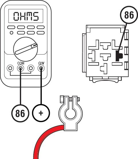
Compare reading(s) in table.
If readings are out of range, refer to OEM guidelines for repair or replacement of vehicle harness to 20-Way TCM Vehicle Harness Connector. Go to Step V
If readings are in range, Go to Step J
| Pins | Range | Reading(s) |
|---|---|---|
| 86 to Ground | Open Circuit (OL) | |
| 86 to Battery Positive (+) | Open Circuit (OL) |
Key off.
Reconnect all connectors and verify all components are properly installed.
Key on with engine off.
Connect ServiceRanger.
Go To “Fault Codes”.
Retrieve and record transmission fault codes, FMIs, occurrences, and timestamps.
If Fault Code 120 is Inactive, the intermittent nature of the fault makes it likely there is a wiring problem between the SER and 20-Way TCM Vehicle Connector. Refer to OEM guidelines for repair or replacement of the vehicle harness. Go to Step V
If Fault Code 120 is Active and no fault was found with vehicle SER wiring, replace Transmission Control Module (TCM). Go to Step V
Note: If troubleshooting indicates no fault found in wiring or connections to TCM, ensure an intermittent issue does not exist in wiring or connections before replacing TCM.
Key off.
Note: FC 120 FMI 7 will only set Active during engine cranking.
Allow TCM to power down.
Key on with engine off
Connect ServiceRanger.
Go To “Fault Codes”.
Retrieve and record transmission fault codes, FMIs, occurrences, and timestamps.
Verify Fault Code 120 FMI 7 is Inactive.
If Fault Code 120 FMI 7 is Inactive and engine cranks, SER may have been incorrectly wired and repaired or bypassed (jumped). Test complete. Go to Step V
If Fault Code 120 FMI 7 sets Active, Go to Step L
Key off.
Remove SER.
Measure resistance between SER socket Pin 30 and Pin 87. Record reading in table.
Note: SER types may vary, refer to OEM wiring diagrams and connector views.
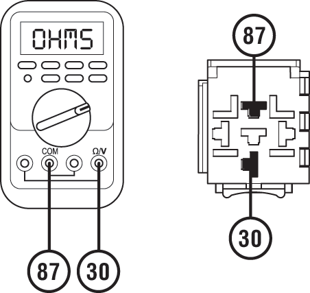
Compare reading(s) in table.
If readings are out of range, refer to OEM guidelines for repair or replacement of SER latch control circuits. Go to Step V
If readings are in range, Go to Step M
| Pins | Range | Reading(s) |
|---|---|---|
| 30 to 87 | Open Circuit (OL) |
Key off
Measure resistance across the SER Pin 30 and Pin 87. Record reading in table.
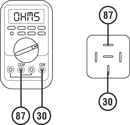
Compare reading(s) in table.
If readings are out of range, refer to OEM guidelines for SER replacement. Go to Step V
If readings are in range, Go to Step V
| Pins | Range | Reading(s) |
|---|---|---|
| 30 to 87 | Open Circuit (OL) |
Key off.
Reconnect all connectors and verify all components are properly installed.
Key on with engine off.
Connect ServiceRanger.
Go To “Fault Codes”.
Select “Clear All Faults”.
Operate vehicle and attempt to reset the fault code or duplicate the previous complaint.
Check for fault codes using ServiceRanger.
If no fault codes set and vehicle operates properly, test complete.
If Fault Code 120 sets Active, Go to Step A
If a fault code other than 120 sets Active, troubleshoot per the Fault Code Isolation Procedure Index.