Fault Code 250: Linear Clutch Actuator (LCA) Position Sensor
J1939: SA 3 SPN 33 FMI 0, 1, 2, 3, 4, 5, 6, 7, 8, 9, 12, 13, 14, 15, 16, 17, 20, 31
Overview
The Endurant XD Series transmissions are equipped with a Linear Clutch Actuator (LCA) Position Sensor to monitor clutch position. The LCA is mounted to the Mechatronic Transmission Module (MTM) and pneumatically controls the clutch position. The LCA contains a magnet that allows the LCA Position Sensor to sense clutch position and provide it to the Transmission Control Module (TCM). The LCA Position Sensor is mounted in the MTM and connected to the TCM at the 74-way Transmission Harness Connector.
Detection
The TCM monitors the LCA Position Sensor signal. If LCA position is outside of normal operating range or a system failure is detected, the fault is set Active.
Conditions to Set Fault Code Active
FMI 0 - Data Valid But Above Normal (Most Severe): Uncommanded clutch movement toward engaged position for 2 seconds.
FMI 1 - Data Valid But Below Normal (Most Severe): Uncommanded clutch movement toward disengaged position for 2 seconds.
FMI 2 – Data Erratic: LCA Position Sensor signal out of range for 1 second.
FMI 3 – Voltage Above Normal or Shorted High: LCA Position Sensor circuit shorted to power for 1 second.
FMI 4 – Voltage Below Normal or Shorted Low: LCA Position Sensor circuit shorted to ground for 1 second.
FMI 5 – Current Below Normal or Open Circuit: LCA Position Sensor circuit open for 1 second.
FMI 6 - Current Above Normal or Grounded Circuit: LCA Position Sensor reference voltage not between 4.75V to 5.25V for 1 second.
FMI 7 - Mechanical System Not Responding: During a clutch calibration the expected fully engaged (closed) clutch position was not achieved.
FMI 8 – Abnormal Frequency: LCA Position Sensor signal frequency out of range for 1 second.
FMI 9 - Abnormal Update Rate: LCA magnet not detected by LCA Position Sensor for 1 second.
FMI 12 – Bad Intelligent Device: LCA Position Sensor circuit self-check failure for 1 second.
FMI 13 – Out Of Calibration: LCA Position Sensor out of calibration.
FMI 14 – Special Instructions: Inappropriate clutch position command relative to torque command.
FMI 15 - Data Valid But Above Normal (Least Severe): During a LCA Position Sensor calibration the Torque Transfer Touch Point clutch position was out of range.
FMI 16 – Data Valid But Above Normal (Moderately Severe): During a LCA Position Sensor calibration the Torque Transfer Touch Point clutch position was not available.
FMI 17 – Data Valid But Below Normal (Least Severe): During a LCA Position Sensor calibration the 10 Nm torque transfer clutch position was out of range.
FMI 20 – Data Drifted High: LCA Position Sensor incorrectly reports clutch is disengaged near engine idle when torque is elevated and service brake is applied.
FMI 31 – Condition Exists: LCA Position Sensor incorrectly reports clutch is disengaged near engine idle when torque is elevated and parking brake is applied.
Fallback
FMI 0, 1, 2, 3, 4, 5, 6, 7, 8, 9, 12, 13, 14, 15, 16, 17, 20, 31:
- Coast Mode and Neutral Coast prohibited
- Urge to Move and Creep Mode prohibited
- Inertia Brake activation prohibited
- Upshifts prohibited
- Clutch engagements prohibited
- Non-Neutral modes prohibited
- PTO Mode prohibited
- If vehicle is moving:
- Red stop lamp on
Conditions to Set Fault Code Inactive
FMI 0, 1: Clutch position in range for 10 seconds.
FMI 2: LCA Position Sensor signal in range for 10 seconds.
FMI 3: LCA Position Sensor circuit not shorted to power for 10 seconds.
FMI 4: LCA Position Sensor circuit not shorted to ground for 10 seconds.
FMI 5: LCA Position Sensor circuit not open for 10 seconds.
FMI 6: LCA Position Sensor reference voltage in range for 10 seconds.
FMI 8: LCA Position Sensor signal frequency in range for 10 seconds.
FMI 9: LCA magnet detected for 10 seconds.
FMI 12: LCA Position Sensor circuit self-checks in range for 10 seconds.
FMI 13: Successful LCA Position Sensor calibration.
FMI 14, 20, 31: Key cycle and fault condition no longer exists.
FMI 7, 15, 16, 17: During LCA position sensor calibration clutch position value was available and in range.
Possible Causes
FMI 0, 1:
- LCA
- Air leak
- Self-adjustment mechanism
- MTM
- Air leak
- MTM - Valve Pack C
- Stuck open clutch exhaust valve(s)
- Clutch Release System
- Release Yoke
- Release Bearing
- MTM - LCA Position Sensor
- Internal failure
FMI 7
- LCA
- Self-adjustment mechanism
- MTM - Valve Pack C
- Stuck open clutch fill valve(s)
- Clutch Release System
- Release Yoke
- Release Bearing
- MTM - LCA Position Sensor
- Internal failure
- Incorrect engine flywheel housing
FMI 15, 16, 17:
- LCA
- Self-adjustment mechanism
- MTM - Valve Pack C
- Stuck open clutch fill valve(s)
- Clutch Release System
- Release Yoke
- Release Bearing
- MTM - LCA Position Sensor
- Internal failure
FMI 2, 3, 4, 5, 6, 8, 20, 31:
- MTM - LCA Position Sensor
- Internal failure
- Damaged
- MTM - Transmission Harness
- Wiring shorted to power, shorted to ground or open
- TCM
- Internal failure
FMI 9:
- LCA
- Magnet Loose
- Magnet Detached
- MTM - LCA Position Sensor
- Loose
- Damaged
- Incorrect engine flywheel housing
FMI 12, 14:
- TCM
- Software issue
- Internal failure
FMI 13:
- Clutch calibration required
Additional Tools
- Endurant XD Service Manual TRSM0960
- Eaton Breakout Box with 74-Way Eaton Diagnostic Adapter - RR1029TR
- Digital Volt Ohm Meter (DVOM)
Component Identification
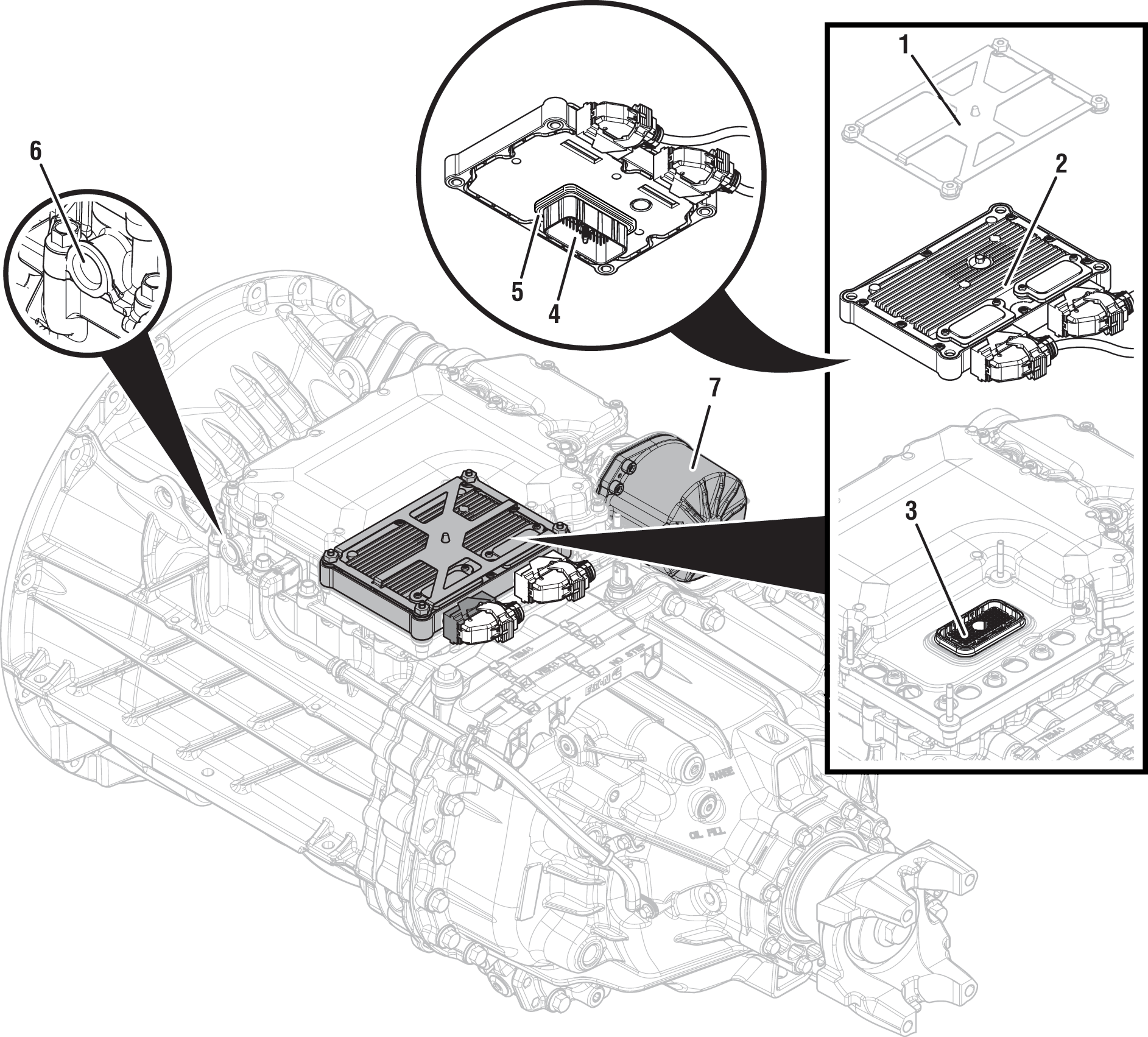 |
1. Transmission Control Module (TCM) Cover 2. Transmission Control Module (TCM) 3. 74-Way Transmission Harness Connector 4. TCM Side of 74-Way TCM Transmission Harness Connector 5. Transmission Control Module (TCM) Seal 6. MTM Air Inlet Port 7. Linear Clutch Actuator (LCA) |
Fault Code 250 Troubleshooting
Set vehicle parking brake and chock wheels.
Record transmission fault codes, FMIs, occurrences, and timestamps from Service Activity Report created during the Diagnostic Procedure.
Note: If the engine flywheel housing was just replaced and Fault Code 250 set immediately after repair, contact OEM and/or engine manufacturer and ensure the correct housing part number was installed based on the transmission model.
If Fault Code 250 FMI 0, 1, 15, 16, 17 is Active or Inactive, Go to Step D
If Fault Code 250 FMI 2, 3, 4, 5, 6, 8, 20, 31 is Active or Inactive, Go to Step B
If Fault Code 250 FMI 7 is Active or Inactive, Go to Step G
If Fault Code 250 FMI 9 is Active or Inactive, Go to Step E
If Fault Code 250 FMI 12, 14 is Active or Inactive, Go to Step F
If Fault Code 250 FMI 13 is Active, perform the Clutch Calibration with ServiceRanger. Test complete, Go to Step V
If Fault Code 250 FMI 13 is Inactive, Clutch Calibration already performed. Test complete, Go to Step V
Key off.
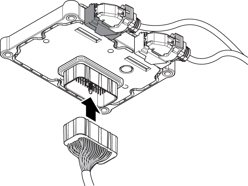
Remove TCM from MTM with 20-Way TCM Vehicle Harness Connector and 20-Way TCM Body Harness Connector connected.

Inspect TCM side of the 74-Way Transmission Harness Connector, verify connector is free from contamination and corrosion; terminals are not bent, spread or loose; and there is no damage to connector body.
Inspect TCM Seal, verify seal is properly installed and there is no damage.
If contamination or damage is found, replace Transmission Control Module (TCM) and Mechatronic Transmission Module (MTM). Go to Step V
Note: MTM removal and installation requires transmission be removed from vehicle. Reference Endurant XD Service Manual TRSM0960, Transmission Removal Service Procedure.
If no contamination or damage is found, Go to Step C
Key off.
Connect Eaton Breakout Box with 74-Way Eaton Diagnostic Adapter to TCM 74-Way Connector.
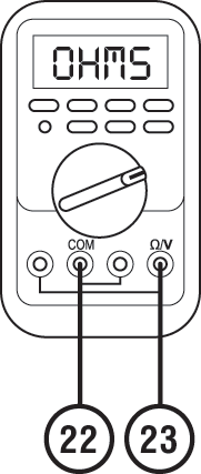
Measure resistance at Eaton Breakout Box between Pin 22 and Pin 23. Record reading in table.
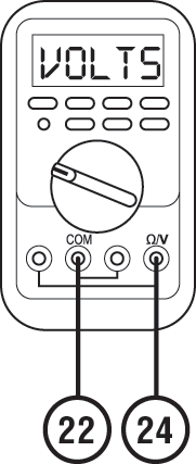
Key on.
Measure voltage at Eaton Breakout Box between Pin 22 and Pin 24. Record reading in table.
Compare reading(s) in table.
If readings are in range, replace Mechatronic Transmission Module (MTM). Go to Step V
Note: MTM removal and installation requires transmission be removed from vehicle. Reference Endurant XD Service Manual TRSM0960, Transmission Removal Service Procedure.
If readings are out of range, replace Transmission Control Module (TCM). Go to Step V
| Ignition State | Pins | Range | Reading(s) |
|---|---|---|---|
| Key off | 22 to 23 | 7.5k- 22k Ohms | |
| Key on | 22 to 24 | 4.75-5.25 V |
Key off.
Refer to OEM guidelines and vent vehicle air supply line to MTM.
Refer to OEM guidelines and remove vehicle air supply line at MTM.
Inspect vehicle air supply line and MTM air inlet port for contamination, moisture, corrosion and/or debris.
Note: Verify MTM inlet screen is installed and free of contamination and/or debris.

If contamination is found, refer to OEM guidelines for repair or replacement of vehicle air system. Replace Mechatronic Transmission Module (MTM) and Inertia Brake Assembly. Go to Step V
Note: MTM removal and installation requires transmission be removed from vehicle. Reference Endurant XD Service Manual TRSM0960, Transmission Removal Service Procedure.
If no contamination is found, Go to Step E
Key off.
Disconnect 20-Way TCM Vehicle Harness Connector.
Remove the LCA.
NoticeInspect the LCA Position Sensor Magnet.

Inspect LCA to MTM Seal.
Inspect the LCA to MTM sealing surface on the MTM.
Inspect LCA Position Sensor in the MTM through the LCA mounting opening and verify the LCA Position Sensor is properly secured.
Note: Fault Code 250 FMI 9 sets Active if the LCA is removed with the key on (TCM powered up).
If the LCA Position Sensor Magnet is damaged and no other fault is found, replace the Linear Clutch Actuator (LCA). Go to Step V
If the LCA to MTM Seal is damaged and no fault is found with the LCA to MTM sealing surface on the MTM, replace the Linear Clutch Actuator (LCA). Go to Step V
If the LCA to MTM sealing surface on the MTM is damaged, replace Mechatronic Transmission Module (MTM) (includes LCA). Go to Step V
If the LCA Position Sensor in the MTM is not properly secured, replace Mechatronic Transmission Module (MTM) (includes LCA). Go to Step V
Note: MTM removal and installation requires transmission be removed from vehicle. Reference Endurant XD Service Manual TRSM0960, Transmission Removal Service Procedure.
If no fault is found with the LCA, MTM or LCA Position Sensor, Contact Eaton Cummins Automated Transmission Technologies for further diagnostic instructions. For Help Line phone numbers, go to Contact Information. Go to Step V
Key off.
Allow TCM to perform a complete power down.
Key on with engine off.
Connect ServiceRanger.
Go to “Programming”.
Under "Software Information", record TCM software in table.
If a TCM software update is available, update TCM software. Go to Step V
If the TCM is at the latest available software, Contact Eaton Cummins Automated Transmission Technologies for further diagnostic instructions. For Help Line phone numbers, go to Contact Information. Go to Step V
| TCM Software |
|---|
Key off.
Disconnect 20-Way TCM Vehicle Harness Connector.
Remove the LCA.
NoticeUsing steel ruler or suitable measurement device, measure distance from Release Yoke to LCA mounting surface.
Notice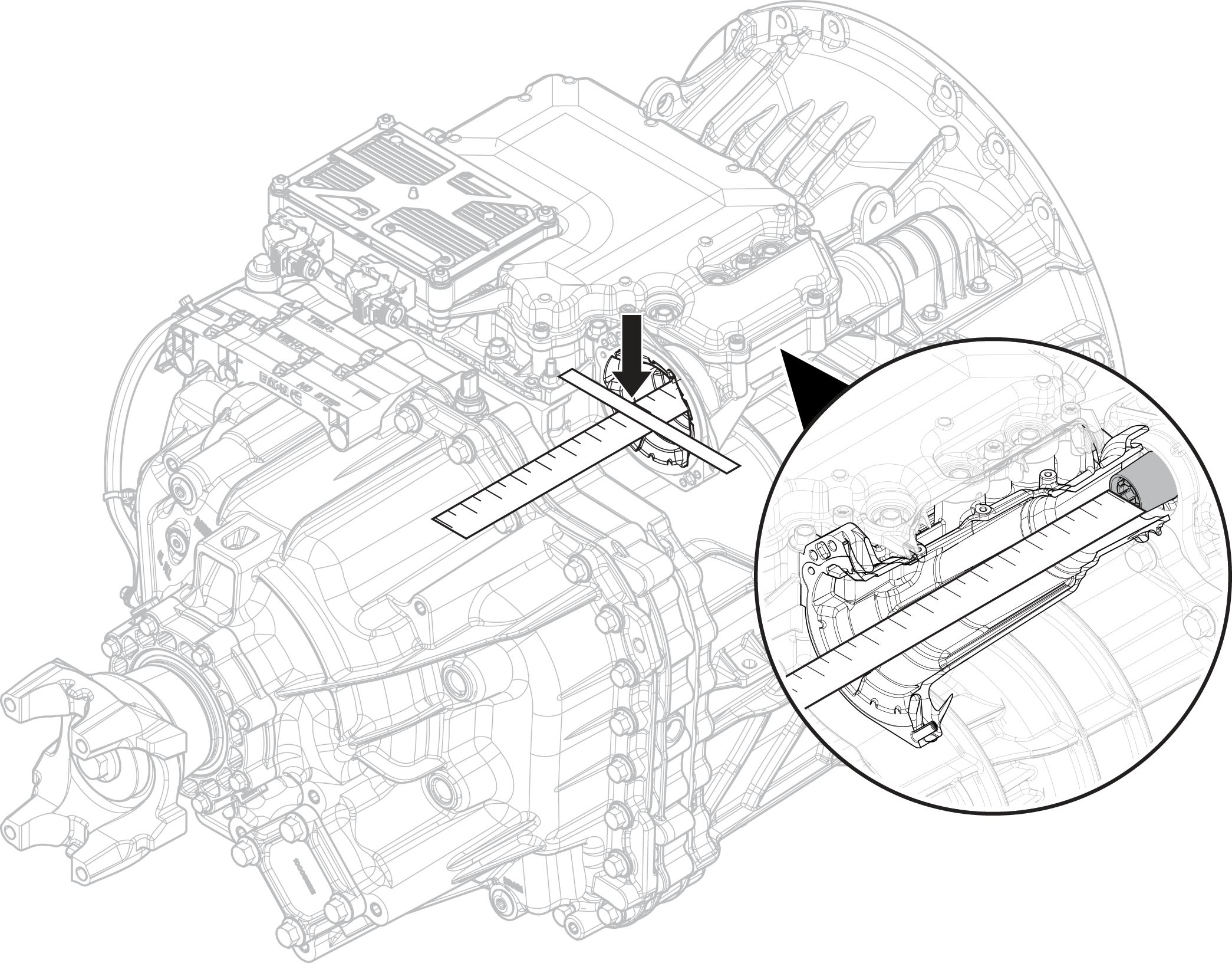
Record measurement in table.
If reading is less than 276 mm (10 13/16”), contact OEM and/or engine manufacturer and ensure the correct engine flywheel housing part number was installed based on the transmission model. Go to Step V
If reading is greater than 290 mm (11 7/16”), reference the Clutch Service Procedure for replacement of the Clutch Assembly. Go to Step V
If reading is between 276 – 290 mm (10 13/16” – 11 7/16”), contact Eaton Cummins Automated Transmission Technologies at +1-800-826-4357 for further diagnostic instructions. Go to Step V
| Release Yoke to LCA Mounting Surface Distance | Measurement |
|---|---|
| 276 – 290 mm (10 13/16” – 11 7/16”) |
Key off.
Reconnect all connectors and verify all components are properly installed.
Key on with engine off.
Connect ServiceRanger.
Go To “Fault Codes”.
Select “Clear All Faults”.
Operate vehicle and attempt to reset the fault code or duplicate the previous complaint.
Check for fault codes using ServiceRanger.
If no fault codes set and vehicle operates properly, test complete.
If Fault Code 250 sets Active, Go to Step A
If a fault code other than 250 sets Active, troubleshoot per the Fault Code Isolation Procedure Index.