Fault Code 295: Rail C Position
J1939: SA 3 SPN 4220 FMI 0, 1, 2, 3, 4, 5, 6, 7, 8, 9, 10, 12, 14, 15, 16, 17, 18, 20, 21, 31
Overview
The Endurant XD Series transmissions are equipped with 5 shift rail position sensors and 5 magnets mounted shift rails A, B, C, D and E. The shift rail positions sensors monitor the position of the shift rail magnet and provide the information to the Transmission Control Module for the purpose of making shift decisions, confirming gear engagement, and monitoring shift rail positions. Shift Rail C actuates the Rail C Sliding Clutch to engage the Splitter Gear or Driven Gear 2nd. The position sensors are located in the Mechatronic Transmission Module (MTM) and connected to the Transmission Control Module (TCM) at the 74-Way Transmission Harness Connector.
Detection
The TCM monitors Shift Rail C position. If a system failure is detected, the fault is set Active.
Conditions to Set Fault Code Active
FMI 0 – Data Valid But Above Normal (Most Severe): Shift Rail C movement beyond the calibrated Splitter Gear engagement position for 1 second.
FMI 1 – Data Valid But Below Normal (Most Severe): Shift Rail C movement beyond the calibrated Driven Gear 2nd engagement position for 1 second.
FMI 2 – Data Erratic: Rail C Position duty cycle out of range for 1 second.
FMI 3 – Voltage Above Normal or Shorted High: Rail C Position Sensor circuit shorted to power for 1 second.
FMI 4 – Voltage Below Normal or Shorted Low: Rail C Position Sensor circuit shorted to ground for 1 second.
FMI 5 – Current Below Normal or Open Circuit: Rail C Position Sensor circuit open for 1 second.
FMI 6 – Current Above Normal or Grounded Circuit: Rail C Position Sensor signal out of normal operating voltage (4.75V to 5.25V) for 1 second.
FMI 7 – Mechanical System Not Responding: Shift Rail C failed interlock function test. Uncommanded Shift Rail C movement from neutral position while Driven Gear 1st or Reverse Gear was engaged.
FMI 8 – Abnormal Frequency: Rail C Position Sensor signal frequency out of range for 1 second.
FMI 9 – Abnormal Update Rate: Rail C Position Sensor did not detect Shift Rail C magnet for 1 second.
FMI 10 – Abnormal Rate Of Change: Rail C Position value rate of change exceeded when no Shift Rail C movement commanded for 1 second.
FMI 12 – Bad Intelligent Device: Rail C Position Sensor circuit self-check failure for 1 second.
FMI 14 – Special Instructions: Rail C Position value indicated Driven Gear 2nd engagement position, but Rail D Position Sensor and speed sensors confirmed Driven Gear 1st or Reverse Gear engagement for 1 second.
FMI 15 - Data Valid but Above Normal (Least Severe): Uncommanded Shift Rail C movement from neutral position toward Splitter Gear while Driven Gear 1st or Reverse Gear was engaged for 2 seconds.
FMI 16 - Data Valid but Above Normal (Moderately Severe): Uncommanded Shift Rail C movement from Splitter Gear toward neutral position while speed sensors continued to indicate a Splitter Gear ratio.
FMI 17 – Data Valid but Below Normal (Least Severe): Uncommanded Shift Rail C movement from neutral position toward Driven Gear 2nd while Driven Gear 1st or Reverse Gear was engaged for 2 seconds.
FMI 18 – Data Valid but Below Normal (Moderately Severe): Uncommanded Shift Rail C movement from Driven Gear 2nd toward neutral position while speed sensors continued to indicate a Driven Gear 2nd ratio.
FMI 20 – Data Drifted High: Rail C Position value indicated Splitter Gear disengagement but speed sensors and torque continued to indicate a Splitter Gear ratio for 2 seconds.
FMI 21 – Data Drifted Low: Rail C Position value indicated Driven Gear 2nd disengagement but speed sensors and torque continued to indicate a Driven Gear 2nd ratio for 2 seconds.
FMI 31 – Condition Exists: Rail C Position value indicated Splitter Gear engagement position, but Rail D Position Sensor and speed sensors confirmed Driven Gear 1st or Reverse Gear engagement for 1 second.
Fallback
FMI 0, 1, 2, 3, 4, 5, 6, 8, 9, 10, 12, 14, 15, 16, 17, 18, 20, 21, 31
- If Rail C position is known and Rail C is either fully engaged or disengaged:
- Amber warning lamp on
- Shift Rail C movement prohibited
- If Rail C position is not known and Rail C is either not fully engaged or disengaged:
- Amber warning lamp on
- Shift Rail C movement prohibited
- Inertia Brake activation prohibited
- Non-Neutral modes prohibited
- PTO Mode Prohibited
- If vehicle is moving - Red stop lamp on
FMI 7
- Amber warning lamp on
- No degraded modes
Conditions to Set Fault Code Inactive
FMI 0, 1, 7, 10, 14, 15, 16, 17, 18, 20, 21, 31: Key cycle and fault condition no longer exist.
FMI 2: Rail C Position duty cycle in range for 10 seconds.
FMI 3: Rail C Position Sensor circuit not shorted to power for 10 seconds.
FMI 4: Rail C Position Sensor circuit not shorted to ground for 10 seconds.
FMI 5: Rail C Position Sensor circuit not open for 10 seconds.
FMI 6: Rail C Position Sensor signal voltage between 4.75 and 5.25 volts for 10 seconds.
FMI 8: Rail C Position Sensor signal frequency in range for 10 seconds.
FMI 9: Shift Rail C magnet detected for 10 seconds.
FMI 12: Rail C Position Sensor circuit self-checks in range for 10 seconds.
Possible Causes
FMI 0, 1:
- MTM
- Rail C Yoke
- Internal Transmission
- Rail C Sliding Clutch
FMI 2, 3, 4, 5, 6, 8:
- MTM - Rail C Position Sensor
- Damaged
- Internal failure
- MTM - Transmission Harness
- Wiring shorted to power, shorted to ground or open.
- TCM
- Software issue
- Internal failure
FMI 7:
- MTM - Rail C
- Valve Pack B
- Valve Pack C
- Rail C cylinder
- Rail C yoke
- Rail C detent
- Internal Transmission
- Rail C sliding clutch
- Main Shaft
FMI 9:
- MTM - Rail C Cylinder
- Magnet loose
- Magnet detached
- MTM - Rail C Position Sensor
- Loose
- Damaged
FMI 12:
- TCM
- Software issue
- Internal failure
FMI 10, 14, 20, 21, 31:
- MTM- Rail C Position Sensor
- Internal failure
FMI 15, 16, 17, 18:
- MTM - Rail C Position Sensor
- Internal failure
- MTM - Rail C Detent
- Weak or broken spring
- Worn shift rail or detent
Additional Tools
- Endurant XD Service Manual TRSM0960
- Eaton Breakout Box with 74-Way Eaton Diagnostic Adapter - RR1029TR
- Digital Volt/Ohm Meter (DVOM)
Component Identification
 |
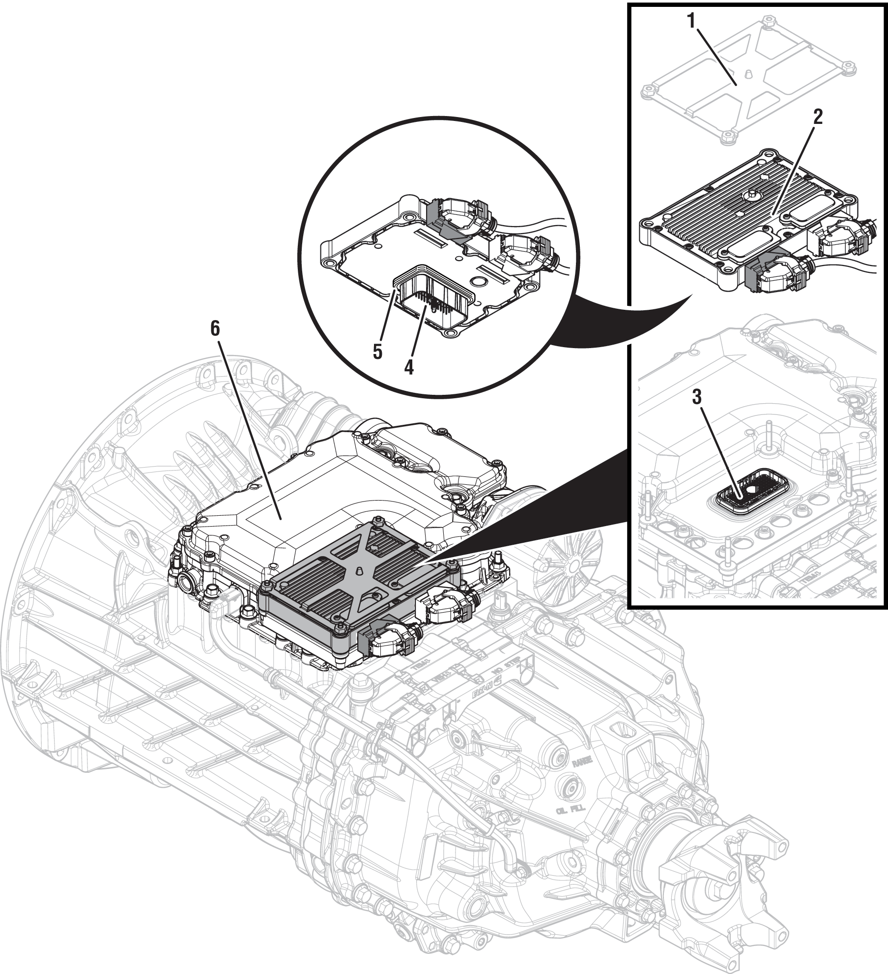
1. Transmission Control Module (TCM) Cover 2. Transmission Control Module (TCM) 3. 74-Way Transmission Harness Connector (TCM-side) 4. 74-Way Transmission Harness Connector (MTM-side) 5. Transmission Control Module (TCM) Seal 6. Mechatronic Transmission Module (MTM) |
Fault Code 295 Troubleshooting
Set vehicle parking brake and chock wheels.
Record transmission fault codes, FMIs, occurrences, and timestamps from Service Activity Report created during the Diagnostic Procedure.
If Fault Code 295 FMI 2, 3, 4, 5, 6, 8, 9, 10, 14, 15, 16, 17, 18, 20, 21, 31 is Active or Inactive, Go to Step B
If Fault Code 295 FMI 0, 1, 7 is Active or Inactive, Go to Step D
If Fault Code 295 FMI 12 is Active or Inactive, Contact Eaton Cummins Automated Transmission Technologies for further diagnostic instructions. For Help Line phone numbers, go to Contact Information. Go to Step V
Key off.
Remove the TCM from the MTM with the 20-Way TCM Vehicle Harness Connector and 20-Way TCM Body Harness Connector20-Way TCM Vehicle Harness Connector and 20-Way TCM Body Harness Connector connected.

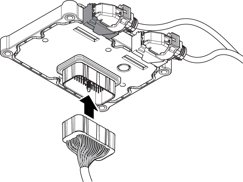
Inspect the TCM side of the 74-Way Transmission Harness Connector, verify the connector is free from any corrosion; the terminals are not bent, spread or loose; and there is no damage to the connector body.
Inspect TCM Seal, verify seal is properly installed and not damaged.
If contamination or damage is found, replace Transmission Control Module (TCM) and Mechatronic Transmission Module (MTM). Go to Step V
Note: MTM removal and installation requires transmission be removed from vehicle. Reference Endurant XD Service Manual TRSM0960, Transmission Removal Service Procedure.
If no contamination or damage is found, Go to Step C
Key off.
Connect Eaton Breakout Box with 74-Way Eaton Diagnostic Adapter to TCM 74-Way Connector.

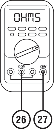
Measure resistance at Eaton Breakout Box between Pin 26 and Pin 27. Record reading in table.

Key on.
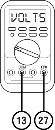
Measure voltage at Eaton Breakout Box between Pin 13 and Pin 27. Record reading in table.

Compare reading(s) in table.
If readings are in range, replace Mechatronic Transmission Module (MTM). Go to Step V
Note: MTM removal and installation requires transmission be removed from vehicle. Reference Endurant XD Service Manual TRSM0960, Transmission Removal Service Procedure.
If readings are out of range, replace Transmission Control Module (TCM). Go to Step V
| Ignition State | Pins | Range | Reading(s) |
|---|---|---|---|
| Key off | 26 to 27 | 7.5k–22k Ohms | |
| Key on | 13 to 27 | 4.75–5.25 V |
Key off.
Remove MTM.
Note: MTM removal and installation requires transmission be removed from vehicle. Reference Endurant XD Service Manual TRSM0960, Transmission Removal Service Procedure.
Inspect Splitter Gear for excessive fore and aft movement.

Inspect Driven Gear 2nd for excessive fore and aft movement.
If excessive gear movement is evident, inspect Main Shaft for cause of excessive movement and repair. Go to Step V
If no excessive gear movement is evident, Go to Step E
Inspect Rail C Sliding Clutch yoke slot for wear.

Shift Rail C Sliding Clutch into neutral position (if necessary).
Shift Rail C Sliding Clutch into Splitter Gear engagement position (fore) and return to neutral.
Shift Rail C Sliding Clutch into Driven Gear 2nd engagement position (aft) and return to neutral.
If Rail C Sliding Clutch shifts into all three positions, replace Mechatronic Transmission Module (MTM). Go to Step V
If Rail C Sliding Clutch does not shift into all three positions, Go to Step F
Inspect Rail C Yoke for wear.

If no yoke wear is evident, inspect Rail C Sliding Clutch and Main Shaft for cause of restricted movement and repair. Go to Step V
If yoke wear is evident, inspect Rail C Sliding Clutch and Main Shaft for cause of restricted movement and repair. Replace Mechatronic Transmission Module (MTM). Go to Step V
Key off.
Reconnect all connectors and verify all components are properly installed.
Key on with engine off.
Connect ServiceRanger.
Go To “Fault Codes”.
Select “Clear All Faults”.
Operate vehicle and attempt to reset the fault code or duplicate the previous complaint.
Check for fault codes using ServiceRanger.
If no fault codes set and vehicle operates properly, test complete.
If Fault Code 295 sets Active, Go to Step A
If a fault code other than 295 sets Active, troubleshoot per Fault Code Isolation Procedure Index.